
基于51单片机的pwm直流电机调速霍尔元件测速系统(可实现按键控制、蓝牙控制、语音控制)(包含所有资料)
基于51单片机的直流电机调速及霍尔元件测速系统(按键、蓝牙、语音识别控制、实物pcb、代码、protues仿真全套资料)
一、项目简介
本项目使用stc89c52rc作为主控芯片所有元器件pcb版图均使用嘉立创绘制,结构原理简单适合一般51单片机课程设计参考。本项目基础功能为按键控制直流电机加减速、正反转。LCD1602显示电机工作状态,占空比/挡位,转速。直流电机测速使用的是霍尔元件,霍尔元件的电路原理这里就不再赘述了,大致就是检测到靠近霍尔元件的磁极变化输出电平会反转,通过电平反转可以得到脉冲,我并没有购买径向多级磁铁(主要是没找到不要运费的)。在转盘或者叶子上用502沾一个小磁铁,一定要搞清楚你的霍尔元件是哪一级电平跳变,不要沾反了那样就测不出来转速了。这样的话,电机每转一圈霍尔元件就会向单片机输出一个脉冲,通过换算和程序定时可以计算出电机转速,不过这个值只是大概值并不准确,大概的话只能精确到十位,个位就没办法了。protues仿真中的编码器电机默认是一圈24个脉冲,这样的话大概就可以准确到小数点后一位。(亲测有效)。
二、实物图

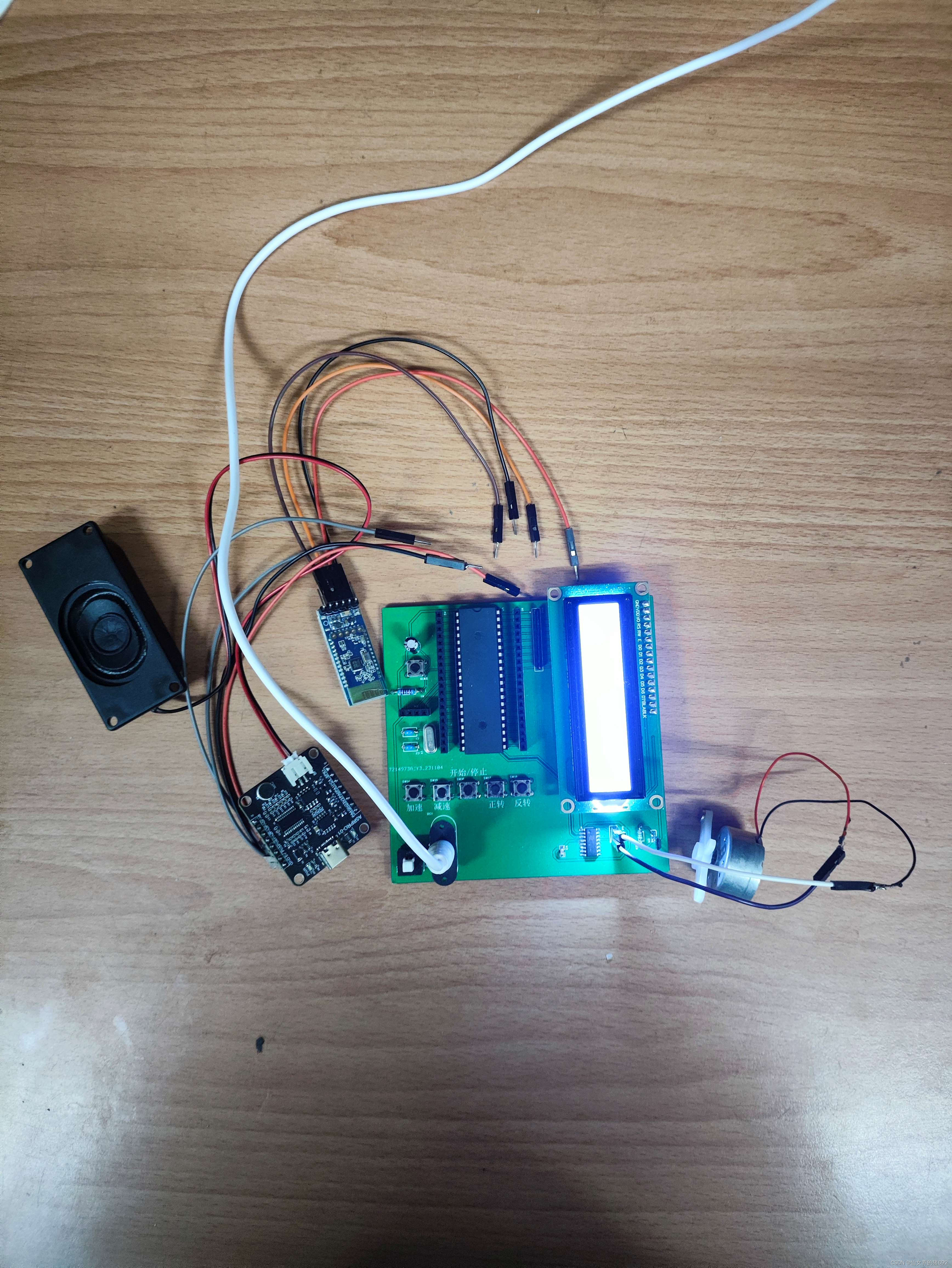
蓝牙模块采用的是hc05,语音识别模块采用的是AROPRO天问开发板,电机是R300C直流小电机通过usb转dc 5v电源线供电。
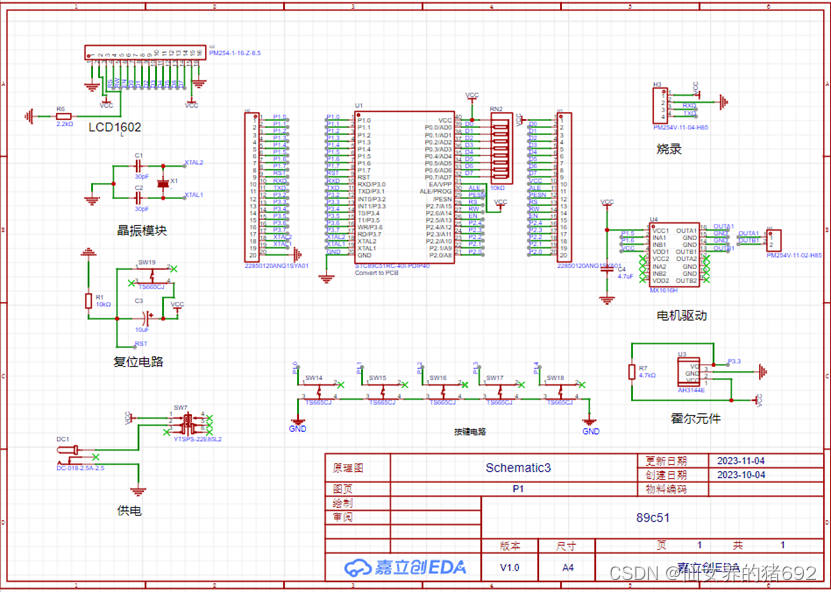
三、原理图
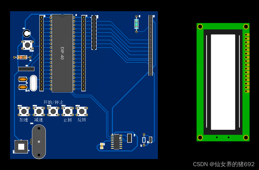
四、PCB

五、代码
因为篇幅有限这里就只放按键控制和蓝牙(可同时控制不冲突)代码
#include <REGX52.H>

sbit Motor_straight=P1^5;
sbit Motor_reverse=P1^6;
//LCD1062引脚配置:
sbit LCD_RS=P2^7;
sbit LCD_RW=P2^6;
sbit LCD_EN=P2^5;
#define LCD_DataPort P0

unsigned char count_f=0,receiveData,KeyNum; //编码器脉冲数
unsigned char count_10ms=0; //10ms计数
float speed_real=0; //转速中间变量
unsigned int speed_result=0; //转速r/min
unsigned char count_motor=0; //滤波变量
unsigned char Counter,Compare=0;	//计数值和比较值,用于输出PWM
unsigned char Speed,straight=1,reverse=0,on=0;

void Delay(unsigned int xms) //延时函数
{
	unsigned char i, j;
	while(xms--)
	{
		i = 2;
		j = 239;
		do
		{
			while (--j);
		} while (--i);
	}
}

unsigned char Key() //按键扫描
{
	unsigned char KeyNumber=0;

	if(receiveData==0x01 || P1_0==0){Delay(20);while(receiveData==0x01 || P1_0==0);Delay(20);KeyNumber=1;}
	if(receiveData==0x02 || P1_1==0){Delay(20);while(receiveData==0x02 || P1_1==0);Delay(20);KeyNumber=2;}
	if(receiveData==0x03 || P1_2==0){Delay(20);while(receiveData==0x03 || P1_2==0);Delay(20);KeyNumber=3;}
	if(receiveData==0x04 || P1_3==0){Delay(20);while(receiveData==0x04 || P1_3==0);Delay(20);KeyNumber=4;}
	if(receiveData==0x05 || P1_4==0){Delay(20);while(receiveData==0x05 || P1_4==0);Delay(20);KeyNumber=5;}
	return KeyNumber;
}


void timer_Init()
{
	TMOD=0X11;
	TL0 = 0x9C;		//设置定时器初值100us
	TH0 = 0xFF;
	TH1=0XD8; //设置定时器初值10ms
	TL1=0XF0;
	TF0=0; //清除溢出标志
	TF1=1;
	ET0=1; //定时中断允许
	ET1=1;
	EA=1; //总中断
	IT1=1; //外部中断
	EX1=1; //下降沿触发
	TR0=1; //定时器开
	TR1=1;
}

void Uart_Init()   //9600bps@11.0592MHz
{
	RCAP2L=0xD9;//9600波特率对应 FFD9,低位为D9
	RCAP2H=0xFF;//高位为FF
	T2CON=0x34;//RCLK、TCLK、TR2置1
	SCON=0x50;//串口工作模式1,接收使能
	ES=1;//打开接收中断
	EA=1;//打开总中断
}

void LCD_Delay() //LCD1602延时函数,12MHz调用可延时1ms
{
	unsigned char i, j;

	i = 2;
	j = 239;
	do
	{
		while (--j);
	} while (--i);
}

void LCD_WriteCommand(unsigned char Command) //LCD1602写命令
{
	LCD_RS=0;
	LCD_RW=0;
	LCD_DataPort=Command;
	LCD_EN=1;
	LCD_Delay();
	LCD_EN=0;
	LCD_Delay();
}

void LCD_WriteData(unsigned char Data) //LCD1602写数据
{
	LCD_RS=1;
	LCD_RW=0;
	LCD_DataPort=Data;
	LCD_EN=1;
	LCD_Delay();
	LCD_EN=0;
	LCD_Delay();
}

void LCD_SetCursor(unsigned char Line,unsigned char Column) //LCD1602设置行,列数 1~2行,1~16列
{
	if(Line==1)
	{
		LCD_WriteCommand(0x80|(Column-1));
	}
	else if(Line==2)
	{
		LCD_WriteCommand(0x80|(Column-1+0x40));
	}
}

void LCD_Init() //LCD1602初始化函数
{
	LCD_WriteCommand(0x38);//八位数据接口,两行显示,5*7点阵
	LCD_WriteCommand(0x0c);//显示开,光标关,闪烁关
	LCD_WriteCommand(0x06);//数据读写操作后,光标自动加一,画面不动
	LCD_WriteCommand(0x01);//光标复位,清屏
}

在LCD1602指定位置上显示一个字符
//void LCD_ShowChar(unsigned char Line,unsigned char Column,char Char)
//{
//	LCD_SetCursor(Line,Column);
//	LCD_WriteData(Char);
//}

//在LCD1602指定位置开始显示所给字符串
void LCD_ShowString(unsigned char Line,unsigned char Column,char *String)
{
	unsigned char i;
	LCD_SetCursor(Line,Column);
	for(i=0;String[i]!='\0';i++)
	{
		LCD_WriteData(String[i]);
	}
}

//返回值=X的Y次方
int LCD_Pow(int X,int Y)
{
	unsigned char i;
	int Result=1;
	for(i=0;i<Y;i++)
	{
		Result*=X;
	}
	return Result;
}

//在LCD1602指定位置开始显示所给数字
//Line 起始行位置,范围:1~2
//Column 起始列位置,范围:1~16
//Number 要显示的数字,范围:0~65535
//Length 要显示数字的长度,范围:1~5
void LCD_ShowNum(unsigned char Line,unsigned char Column,unsigned int Number,unsigned char Length)
{
	unsigned char i;
	LCD_SetCursor(Line,Column);
	for(i=Length;i>0;i--)
	{
		LCD_WriteData(Number/LCD_Pow(10,i-1)%10+'0');
	}
}

void main()
{
	Uart_Init();
	timer_Init();
	LCD_Init();
	LCD_ShowString(2,1,"DC:");
	LCD_ShowNum(2,4,Compare,3);
	LCD_ShowString(1,1,"RPM:");
	LCD_ShowNum(1,6,speed_result,4);
	while(1)
	{
		LCD_ShowNum(1,6,speed_result,4);
		//LCD_ShowChar(1,12,'.');
		//LCD_ShowNum(1,13,speed_result%10,1);
		KeyNum=Key();
		if(KeyNum==1)
		{
			Speed++;
			if(Speed==0){Compare=0;}	//设置比较值,改变PWM占空比
			if(Speed==1){Compare=50;LCD_ShowNum(2,4,Compare/2,3);}
			if(Speed==2){Compare=75;LCD_ShowNum(2,4,Compare/2,3);}
			if(Speed==3){Compare=100;LCD_ShowNum(2,4,Compare/2,3);}
			if(Speed==4){Compare=150;LCD_ShowNum(2,4,Compare/2,3);}
			if(Speed==5){Compare=175;LCD_ShowNum(2,4,Compare/2,3);}
			if(Speed>=6){Speed=6;Compare=200;LCD_ShowNum(2,4,Compare/2,3);}
		}
		if(KeyNum==2)
		{
			Speed--;
			if(Speed>100){Speed=0;}
			if(Speed==0){Compare=0;LCD_ShowNum(2,4,Compare,3);}	//设置比较值,改变PWM占空比
			if(Speed==1){Compare=50;LCD_ShowNum(2,4,Compare/2,3);}
			if(Speed==2){Compare=75;LCD_ShowNum(2,4,Compare/2,3);}
			if(Speed==3){Compare=100;LCD_ShowNum(2,4,Compare/2,3);}
			if(Speed==4){Compare=150;LCD_ShowNum(2,4,Compare/2,3);}
			if(Speed==5){Compare=175;LCD_ShowNum(2,4,Compare/2,3);}
			if(Speed>=6&&Speed<100){Compare=200;LCD_ShowNum(2,4,Compare/2,3);}
		}
		if(KeyNum==3)
		{
			on=1-on;
		}
		if(KeyNum==4){straight=1;reverse=0;}
		if(KeyNum==5){reverse=1;straight=0;}
		if(on==1){LCD_ShowString(1,13,"ON ");}
		else{LCD_ShowString(1,13,"OFF");}
		if(straight==1){LCD_ShowString(2,8,"Straight");}
		else{LCD_ShowString(2,8,"Reverse ");}
	}
}

void INT1_Routine() interrupt 2 //外部中断1中断函数
{
	count_f++;
}

void Timer0_Routine() interrupt 1
{
	TL0 = 0x9C;		//设置定时初值
	TH0 = 0xFF;		//设置定时初值
	Counter++;
	Counter%=200;	//计数值变化范围限制在0~199
	if(on==1)
	{
		if(straight==1)
		{
			if(Counter>Compare)	//计数值大于比较值
			{
				Motor_straight=1;		//输出1
				Motor_reverse=1;
			}
			else				//计数值小于比较值
			{
				Motor_straight=0; //输出0
				Motor_reverse=1;
			}
		}
		if(reverse==1)
		{
			if(Counter>Compare)	//计数值大于比较值
			{
				Motor_straight=1;
				Motor_reverse=1;
			}
			else				//计数值小于比较值
			{
				Motor_straight=1;
				Motor_reverse=0;
			}
		}
	}
	if(on==0)
	{Motor_straight=1;Motor_reverse=1;}
}

void Timer1_Routine() interrupt 3
{
	TH1=0XD8;
	TL1=0XF0;
	count_10ms++;
	if(count_10ms==100)
	{
		count_motor=count_f+count_motor;
		count_f=0;
	}
	if(count_10ms==200)
	{
		count_10ms=0;
		count_motor=count_f+count_motor;
		speed_real=count_motor*1.0; //每秒圈数
		speed_result=(int)(speed_real*30); //每分钟转圈数
		count_f=0;
		count_motor=0;
	}
}

void UART_INTERRUPT() interrupt 4
{
	if(RI==1)
	{
		receiveData=SBUF;
		RI = 0;
	}
}
六、仿真

仿真我并没有使用电机驱动芯片,而是自己画了一个H桥方便对直流电机调速更好的理解,实物也试过自己焊H桥电路,不过因为电阻选的过大导致电机供电不足转的太慢了,时间紧迫后来就焊了个电机驱动芯片上面。感兴趣的朋友也可以自行试试。仿真代码略有不同。
七、语音驱动模块
这个在购买语音模块时会有足够的参考资料,而且是图形化编程相对容易,同样是通过串口于单片机通讯,与蓝牙驱动代码略有不同,单总体区别不大。
八、总结
这个小项目是本人完成的一个单片机课设,所述内容均已验证完美实现,欢迎大佬们指正,后续我会将所有相关资料整理附上供大家参考,有任何问题可在评论区留言,都会回复。谢谢!
资料自取:
所有资料均为工程文件,可直接使用,PCB板是第二个可以直接下单打板
http://链接:https://pan.baidu.com/s/1iiy16bHN8aRl_UsdJb6Rag?pwd=cson 提取码:cson

CSDN联合极客时间,共同打造面向开发者的精品内容学习社区,助力成长!
更多推荐


 23
23 0
0- 0


 已为社区贡献1条内容

所有评论(0)