
ROS2下通过micro XRCE-DDS实现PX4基于SLAM位姿定位操作方法详解
本文主要是介绍在ROS2下如何通过micro XRCE-DDS实现PX4基于SLAM位姿的定位,同时结合px4代码进行了详细的分析,基于micro XRCE-DDS把/fmu/in/vehicle_visual_odometry话题桥接到PX4内部的方法,相比于向mavros发送/mavros/vision_pose/pose话题的方法,个人觉得它的优点有两个,一个可以在SLAM运行时动态调整协方差,一个是有reset_counter,能够应对SLAM位姿跳变的情况(比如回环,重定位),这些都是对基于SLAM飞无人机时比较实用的功能。
本文内容较长,目录结构如下
- micro XRCE-DDS (uXRCE-DDS)原理与基本使用
- DDS与ROS2
- DDS-XRCE协议
- micro XRCE-DDS (uXRCE-DDS)
- 部署
- 启动命令
- vehicle_visual_odometry (VehicleOdometry.msg)
- 协方差赋值
- 坐标系赋值
- 时间戳赋值
- PX4和ROS2的时间同步
- reset_counter
- reset_counter + 1后会发生什么
- reset_counter与控制器协同
- reset_counter + 1后会发生什么
- quality
- 坐标系变换
- ROS2转换节点编写
- QoS
- 代码示例
- 相关飞控参数设置
- 检查确认
- 参考资料
在ROS2,我们要实现PX4基于SLAM位姿的定位,一种是还可以像ROS1一样通过向mavros发送/mavros/vision_pose/pose话题实现,还有一种是通过micro XRCE-DDS实现,也就是不用mavros。
两种方法的流程如下,最终都是把SLAM位姿转换为相同的vehicle_visual_odometry uORB消息给到PX4的EKF2模块进行融合。
SLAM位姿话题 → /mavros/vision_pose/pose → mavros → VISION_POSITION_ESTIMATE (102) mavlink消息 → PX4/src/modules/mavlink/mavlink_receiver.cpp → vehicle_visual_odometry(uORB)→ EKF2
SLAM位姿话题 → /fmu/in/vehicle_visual_odometry → Micro XRCE-DDS Agent → uxrce_dds_client(PX4) → vehicle_visual_odometry(uORB)→ EKF2
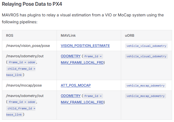
基于micro XRCE-DDS把/fmu/in/vehicle_visual_odometry话题桥接到PX4内部的方法,相比于向mavros发送/mavros/vision_pose/pose话题的方法,它的优点个人觉得,一个可以在SLAM运行时动态调整协方差(准确地讲是方差),一个是reset_counter,能够应对SLAM位姿跳变的情况(比如回环,重定位),都是对于基于SLAM飞无人机比较实用的功能,这些原本在vehicle_visual_odometry(uORB)就有但是/mavros/vision_pose/pose里面没有所以没法实现。协方差赋值和reset_counter这两个点也是本文会详细讲解的两个点,特别是reset_counter。
当然mavros还有个话题可以传SLAM位姿,/mavros/odometry/out,nav_msgs/Odometry.msg类型,这个实际用得比较少,它对应的mavlink消息是ODOMETRY,它可以传递协方差,但是设置不了reset_counter。
https://docs.px4.io/main/zh/ros/external_position_estimation
https://docs.ros.org/en/noetic/api/nav_msgs/html/msg/Odometry.html
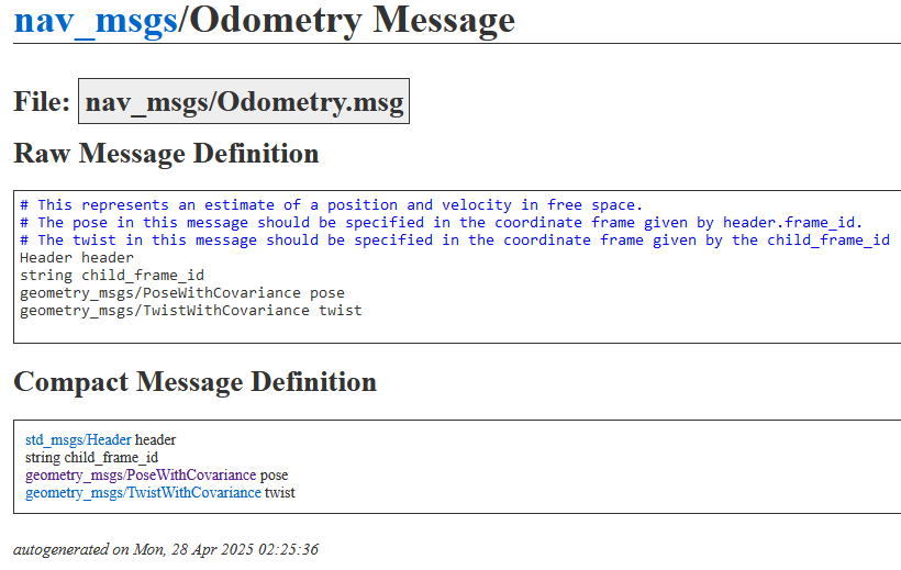
mavlink的ODOMETRY消息倒是和uORB的VehicleOdometry.msg类型高度对应,协方差,reset_counter,甚至quality都有。但还是如上面所说与它对应的mavros话题/mavros/odometry/out(nav_msgs/Odometry.msg类型)没法设置reset_counter。
https://mavlink.io/en/messages/common.html#ODOMETRY
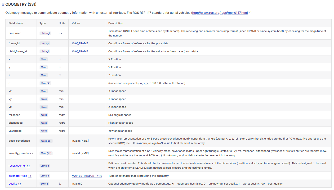
/mavros/vision_pose/pose话题对应的VISION_POSITION_ESTIMATE mavlink消息也有协方差,reset_counter。但/mavros/vision_pose/pose对应的geometry_msgs/PoseStamped.msg类型里面没有协方差,reset_counter。
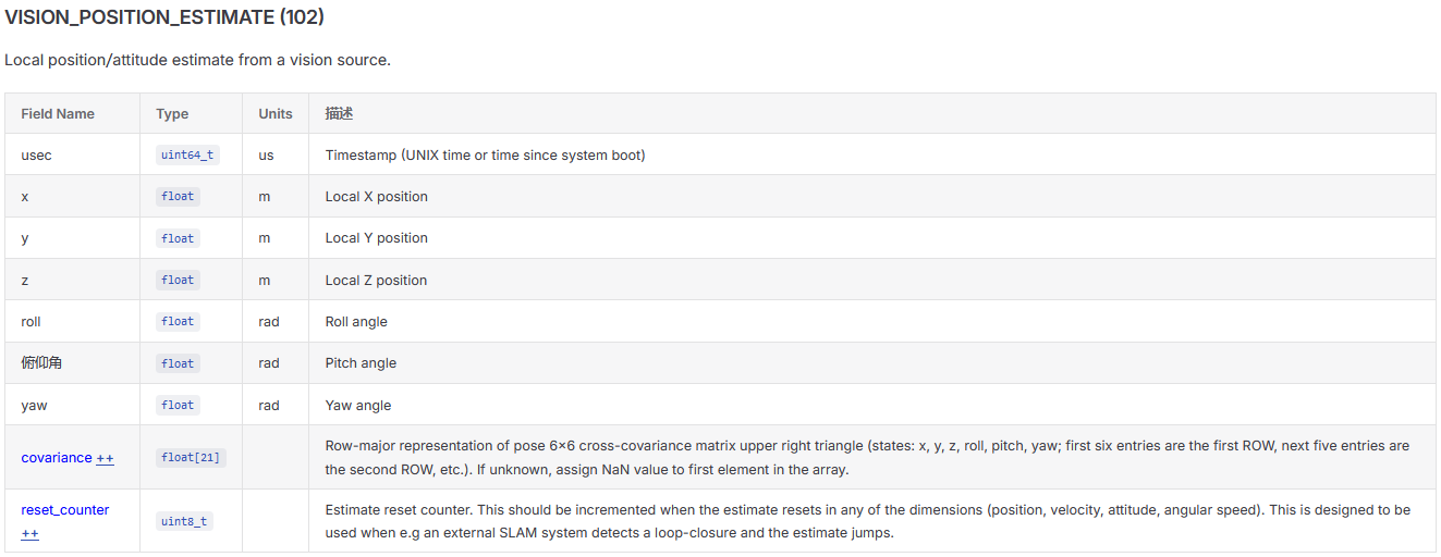
下面将详细讲下通过micro XRCE-DDS实现PX4基于SLAM位姿定位的操作方法,并会结合px4代码进行分析,同时注意本文所涉及的PX4代码是目前PX4 main分支最新代码,如果是较老版本的PX4代码,个别细节上可能会有些出入需要注意。
micro XRCE-DDS(uXRCE-DDS)原理与基本使用
DDS与ROS2
https://www.omg.org/spec/DDS/
DDS(Data Distribution Service,数据分发服务)是 OMG(Object Management Group) 制定的一套标准化中间件协议,其正式规范为 DDS(OMG DDS Specification) ,当前主流版本为 DDS 1.4(2015年发布) ,最新为 DDS 1.5(2022年发布) 。它本质上是一种 以数据为中心的发布-订阅(Publish-Subscribe)通信模型,专为高可靠性、低延迟、高吞吐、强实时性的分布式系统而设计,广泛应用于航空航天、自动驾驶、工业控制、机器人和金融交易等关键领域。
DDS 是 “数据即接口” 的分布式系统通信骨架——开发者定义“要发什么数据”和“要收什么数据”,DDS 自动处理如何可靠、高效、实时地在节点间同步这些数据。
DDS的主流实现包括 Fast DDS、Cyclone DDS、OpenDDS 和 RTI ConnextDDS,分别面向高性能嵌入式、开源生态与高安全关键系统。
DDS(Data Distribution Service)是 ROS 2 的默认且核心的底层通信中间件(Middleware),ROS 2 的通信架构(包括话题发布/订阅、服务调用、参数系统等)均建立在 DDS 的协议与 API 之上;ROS 2 以 DDS 为通信基石,其架构通过 RMW 层(抽象中间件接口)和 rcl 层(客户端库)将 DDS 实现(如 Fast DDS(默认)、Cyclone DDS 等)封装起来,使上层应用(rclcpp/rclpy)无需接触 DDS API,而所有核心通信能力(发现、QoS、可靠性、实时性)仍由 DDS 提供。
ROS 2 应用层(Node, Topic, Service, Action)
        ↓
   rcl(ROS Client Library)—— 实现 ROS 2 API 的客户端库
        ↓
   RMW(ROS Middleware Interface)—— 抽象中间件接口层
        ↓
   DDS 实现层(可替换)
        ├── Fast DDS(默认实现,由 eProsima 提供)
        ├── Cyclone DDS(由 Eclipse 基金会维护)
        ├── RTI Connext DDS(商业级 DDS 实现)
        └── GurumDDS(GurumNetworks 提供)
rcl 层负责将 ROS 2 的高层概念(如 Node::create_publisher())转化为对 RMW 接口的调用;
RMW 层的作用是将 DDS 实现与上层解耦,定义了统一的中间件接口(如 rmw_publish()、rmw_create_subscription()),使上层代码与具体 DDS 实现无关,用户可以在不修改应用代码的情况下,通过环境变量切换底层 DDS 实现;
export RMW_IMPLEMENTATION=rmw_cyclonedds_cpp
DDS 实现层提供实际通信能力;
ROS 1 则是使用自研的 TCPROS/UDPROS(基于 TCP/UDP 的点对点通信)。
DDS-XRCE协议
https://www.omg.org/spec/DDS-XRCE/
https://www.omg.org/spec/DDS-XRCE/1.0/PDF
DDS-XRCE 全称是 DDS For Extremely Resource Constrained Environments 直接翻译的话是 面向资源极度受限环境的 DDS,但需要注意DDS-XRCE并不是某种DDS,DDS是一种分布式数据共享的中间件规范,而DDS-XRCE是一个通信协议。
DDS-XRCE 协议是一种客户端–服务器架构的通信协议,运行于资源受限的设备(即客户端)与 XRCE 代理(Agent,即服务器)之间。该协议使具备休眠/唤醒周期的低功耗设备,能够在带宽受限的网络环境下,接入 DDS 全局数据空间(DDS Global Data Space),实现数据的访问与交互。旨在支持资源受限、低功耗设备(如 MCU)与标准 DDS 网络之间的互操作。传统 DDS 实现(如 Fast DDS、Cyclone DDS)依赖完整操作系统、较大内存(几十 MB)和 TCP/IP 栈,无法直接运行在只有几十 KB RAM 的 MCU 上。DDS-XRCE 通过将“复杂部分”卸载到外部 Agent(通常运行在 Linux 或 RTOS 上),使微控制器仅需实现一个极简的通信客户端。
其核心架构为代理式桥接(Proxy-based Bridging),由两部分组成:
XRCE Client:运行在微控制器端,资源极受限(典型 RAM 占用为几十 KB),仅实现轻量级协议栈(通常 < 100 KB),负责数据序列化/反序列化、会话管理,并通过串口或 UDP 向 Agent 发送 XRCE 协议帧(如创建参与者、主题、发布/订阅请求等)。
XRCE Agent:运行在资源较充裕的平台(如 Linux、RTOS 等),接收 Client 请求后,将其转换为标准 DDS 操作(如 DDS::Publisher/Subscriber),并接入 DDS 域与其他 DDS 实体通信。
客户端(client)和代理(Agent)之间传输的是XRCE协议帧。
XRCE 协议层消息格式(核心结构)
XRCE 消息是 16 字节对齐 的字节序列,由 消息头(Message Header) + 子消息(Submessage) 组成。典型格式如下(以 WRITE_DATA 为例):
0               8               16               24               31
+---------------+----------------+----------------+----------------+
|  session_id   |   stream_id    |          sequenceNr             | 4
+-------+-------+----------------+----------------+----------------+
|  WRITE_DATA   |   flags        |         submessageLength        | 8
+---------------+----------------+----------------+----------------+
|           request_id           |          object_id              | 12
+---------------+----------------+----------------+----------------+
|  info.state   |  FORMAT_EMPTY  |          serialized_data        | 16
+---------------+----------------+----------------+----------------+
                     serialized_data                               | 20
+---------------+----------------+----------------+----------------+
- 消息头(Bytes 0–3)
session_id(4 字节):会话标识符stream_id(4 字节):流标识符(如STREAMID_BUILTIN_RELIABLE = 0x80)sequenceNr(4 字节):消息序列号(小端序)
- 子消息头(Bytes 4–7)
submessageId(1 字节):如WRITE_DATA = 0x07,READ_DATA = 0x07,DATA = 0x06flags(1 字节):- Bit 0 = 1 → 小端序(Little Endian)
- Bits 1–3:指定
DataFormat(如FORMAT_SAMPLE = 0x02)
submessageLength(2 字节):子消息负载长度(小端序)
- 子消息负载(Payload,起始于 Byte 8)
不同子消息类型负载结构不同,常见类型包括:
| 类型 | 说明 | 关键字段 |
|---|---|---|
WRITE_DATA |
发送单个样本 | request_id, object_id, info.state, serialized_data |
READ_DATA(单样本) |
请求单个样本 | request_id, object_id, preferred_stream_id, data_format |
READ_DATA(多样本) |
请求样本序列 | 含 ReadSpecification(含 max_samples, max_elapsed_time, max_rate, min_pace_period 等) |
DATA(响应) |
Agent 返回数据 | 含 request_id, object_id, 以及 XDR 或 XCDR 序列化的样本数据(如 SampleSeq, PackedSamples 等) |
样本数据可选格式包括:
FORMAT_SAMPLE:单样本(含SampleInfo+ 数据)FORMAT_SAMPLE_SEQ:样本序列(每个样本含info+data)FORMAT_PACKED_SAMPLES:压缩打包样本(减少头部开销)
micro XRCE-DDS(uXRCE-DDS)
“u” 代表 micro(微型/微嵌入式) ,即 micro XRCE-DDS,uXRCE-DDS(micro XRCE-DDS) 是 DDS-XRCE 协议对应的代码库,由eProsima公司开发,其目标是使资源受限的设备(例如微控制器)能够像其他 DDS 参与者一样与 DDS 世界进行通信,这也是DDS-XRCE协议的目的。该方案遵循客户端/服务器(client/server)架构,Client:运行在资源受限端(如 PX4),仅负责序列化/反序列化数据,不实现完整 DDS 协议栈,Agent:运行在高性能端(如 ROS 2 主机),是完整 DDS 实现(如 Fast DDS),负责与 DDS 网络交互,通信通过如串口、TCP、UDP传输 XRCE 协议数据包。所以Micro XRCE-DDS是由两个库组成的:Micro XRCE-DDS Client 与 Micro XRCE-DDS Agent。其中,Micro XRCE-DDS Client 是轻量级实体,专为在极端资源受限环境(eXtremely Resource Constrained Environments)中编译和运行而设计;而 Micro XRCE-DDS Agent 则是一个代理(broker),用于在 Client 与 DDS 世界之间建立桥接。(https://github.com/eProsima/Micro-XRCE-DDS 这个github地址不是代码,提供项目总览、文档链接、版本发布说明,真正的代码在https://github.com/eProsima/Micro-XRCE-DDS-Client和https://github.com/eProsima/Micro-XRCE-DDS-Agent)
Micro XRCE-DDS client:https://github.com/eProsima/Micro-XRCE-DDS-Client
Micro XRCE-DDS Agent:https://github.com/eProsima/Micro-XRCE-DDS-Agent
https://micro-xrce-dds.docs.eprosima.com/en/stable/introduction.html
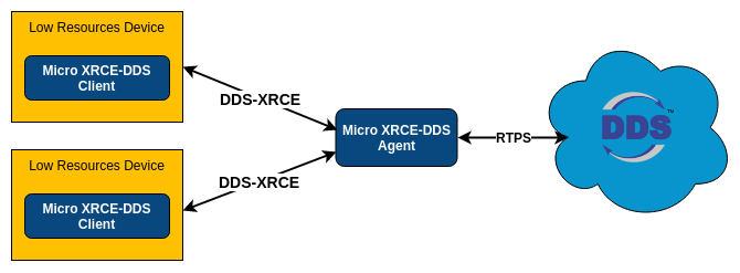
Micro XRCE-DDS 客户端(Client)通过 XRCE 协议向 代理(Agent)发起操作请求,以在 DDS 全局数据空间中实现以下功能:
- 发布(Publish)与订阅(Subscribe) :客户端可请求 Agent 创建对应的 DDS 实体(如 DomainParticipant、Topic、Publisher、Subscriber 等),从而在 DDS 域中发布或订阅指定主题(Topic)的数据;
- 远程过程调用(DDS-RPC) :支持基于 DDS-RPC 标准的请求/应答(request/reply)通信范式,使客户端能以同步或异步方式在 DDS 数据空间中调用远程服务。
Agent 接收并处理这些请求后,返回结构化响应,其内容包括:
- 操作结果状态(如成功、失败、超时等);
- 在订阅或请求类操作中,还一并返回所请求的数据(例如通过 READ_DATA 或 DATA 子消息携带的序列化样本数据)。
Micro XRCE-DDS 为用户提供了 C 语言 API,用于开发 Micro XRCE-DDS 客户端应用程序(比如PX4的uxrce_dds_client)。该库可在编译时通过一组 CMake 标志进行配置:用户可在编译前启用或禁用某些功能配置文件(profiles),并调整若干控制库功能的参数,从而灵活裁剪库的尺寸与资源占用。
Micro XRCE-DDS client(客户端)与Agent(代理)之间的通信可通过多种内置传输方式实现,包括:UDPv4、UDPv6、TCPv4、TCPv6 以及串行(Serial)通信;此外,用户还可自行开发并集成自定义(Custom)传输方式。
https://docs.px4.io/main/zh/middleware/uxrce_dds

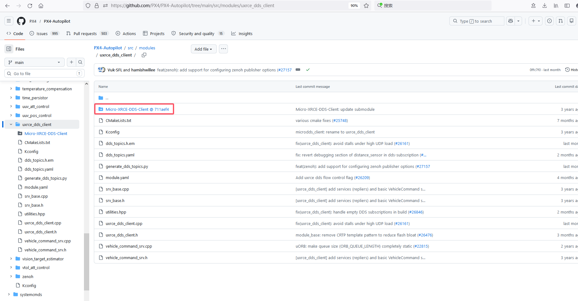
Micro XRCE-DDS client在 PX4 中的使用方式:作为 git submodule 引入,由 uxrce_dds_client 模块调用其 API,https://github.com/PX4/PX4-Autopilot/tree/main/src/modules/uxrce_dds_client
通过在 PX4 飞控端运行 uxrce_dds_client 客户端模块、在机载电脑上运行 Micro XRCE-DDS Agent,将 PX4 内部的 uORB 消息以 DDS/ROS 2 Topic 的形式暴露至外部网络。
SLAM位姿话题 → /fmu/in/vehicle_visual_odometry → Micro XRCE-DDS Agent ↔ uxrce_dds_client(PX4) → vehicle_visual_odometry(uORB)→ EKF2
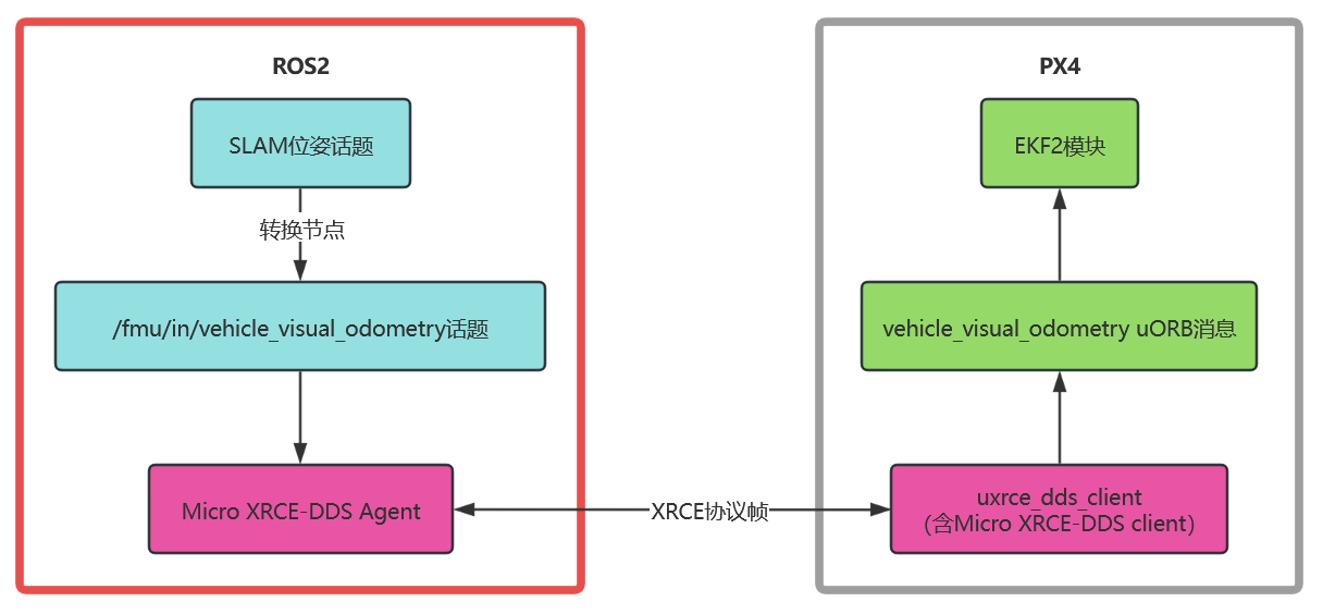
一句话说清楚micro XRCE-DDS在px4和ros2通信中的作用就是:micro XRCE-DDS把px4接入到了ROS2的DDS网络中。
PX4 本身不运行 DDS,它使用自己的轻量级消息总线 uORB;
ROS 2 依赖 DDS 作为底层通信中间件;
Micro XRCE-DDS 通过 Client–Agent 架构,让 PX4 以“瘦客户端”方式(无需完整 DDS 栈)与 DDS 网络交互:
- uxrce_dds_client(PX4 端)负责将 uORB 消息“桥接”为 XRCE 协议数据;
- Micro XRCE-DDS Agent(ROS2 端)作为 DDS Participant,将 XRCE 数据转换为标准 DDS 消息,接入 DDS 域;
最终效果:PX4 的 uORB Topic 可被 ROS 2 节点订阅/发布,PX4 也可订阅 ROS 2 的 DDS Topic —— 即 PX4 成为了 DDS 网络中的一个“逻辑成员”(PX4 并未“成为 DDS Participant” ,而是通过 Agent 代理接入,但实际效果来讲,PX4 等效接入了 DDS 网络)。
部署
PX4 uxrce_dds_client 是在构建时生成,并且默认包含在 PX4 固件中
Micro-XRCE-DDS-Agent需要自己在ROS2端安装
安装步骤如下
git clone -b v2.4.3 https://github.com/eProsima/Micro-XRCE-DDS-Agent.git
cd Micro-XRCE-DDS-Agent
mkdir build
cd build
cmake ..
make
sudo make install
sudo ldconfig /usr/local/lib/
启动命令
Micro-XRCE-DDS-Agent的启动
板载计算机和PX4飞控是基于串口通信的话
假设串口在板载上的驱动是/dev/ACM0,波特率是921600,则Micro-XRCE-DDS-Agent的启动命令如下
sudo MicroXRCEAgent serial --dev /dev/ACM0 -b 921600
客户端启动
uXRCE-DDS 客户端模块(uxrce_dds_client)默认已集成于PX4固件中。启动该模块时,须为其配置合适的通信通道参数,以实现与代理(Agent)的通信。
因为目前PX4飞控一般是通过串口和板载计算机通信,所以这里主要说下串口配置
飞控配置参数UXRCE_DDS_CFG :指定用于连接的端口,例如 TELEM2。
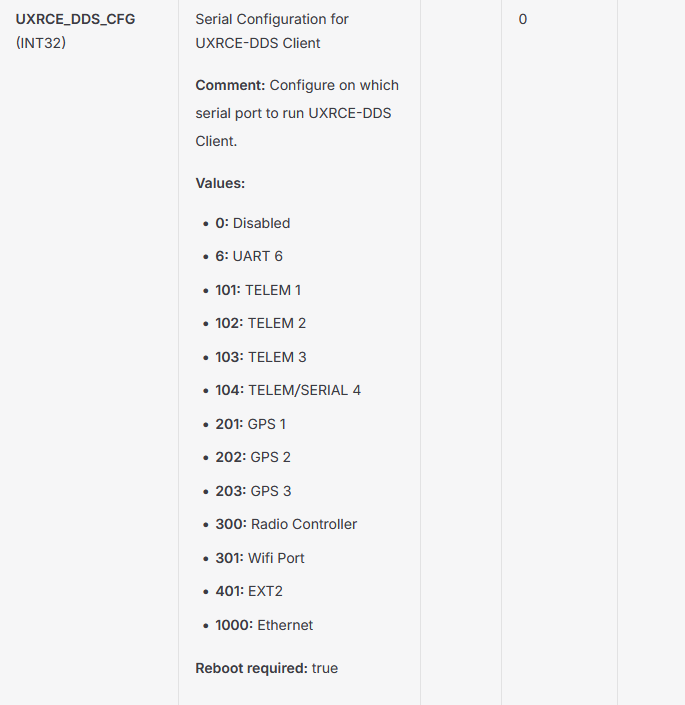
使用对应串口的 _BAUD 参数设置波特率。例如,若通过 TELEM2 连接 companion 计算机,则需配置 SER_TEL2_BAUD。
多数串口已预设默认配置。如需复用这些端口,必须先禁用原有配置:
TELEM1 和 TELEM2 默认分别通过 MAVLink 连接 GCS 与 companion 计算机;可通过将 MAV_0_CONFIG=0 或 MAV_1_CONFIG=0 禁用。
PX4的串口配置可以看 https://docs.px4.io/main/zh/peripherals/serial_configuration#serial-port-configuration
都启动完成后,会有哪些话题发布以及哪些话题可供订阅呢
dds_topics.yaml(PX4-Autopilot\src\modules\uxrce_dds_client\dds_topics.yaml) 文件指定了在构建 PX4 时,哪些 uORB 消息定义会被编译进 uxrce_dds_client 模块中,从而决定了 ROS 2 应用程序可订阅或发布的话题
完整的订阅和发布话题名单可以在下面这个网址查看
https://docs.px4.io/main/zh/middleware/dds_topics
其中就包含我们接下来要分析的/fmu/in/vehicle_visual_odometry,它是px4_msgs::msg::VehicleOdometry类型。
因为我们把 SLAM 位姿通过Micro XRCE-DDS发给 PX4,ROS2端需要做的操作就是把 SLAM 的 nav_msgs/Odometry 或 geometry_msgs/PoseStamped 类型的位姿话题 转成 PX4 的 px4_msgs/VehicleOdometry 类型,发布到 /fmu/in/vehicle_visual_odometry 话题上。
vehicle_visual_odometry(VehicleOdometry.msg)
发布/fmu/in/vehicle_visual_odometry消息的功能包需要包含px4_msgs。
https://github.com/PX4/px4_msgs
/fmu/in/vehicle_visual_odometry消息是VehicleOdometry.msg类型
经由uxrce_dds_client发出的vehicle_visual_odometry uORB消息(topic)同样是VehicleOdometry.msg类型,vehicle_visual_odometry是对应的消息(topic)名称。有多个uORB消息(topic)都是VehicleOdometry.msg类型,包括vehicle_odometry vehicle_mocap_odometry vehicle_visual_odometry estimator_odometry。
VehicleOdometry.msg类型的定义如下
# Vehicle odometry data
#
# Fits ROS REP 147 for aerial vehicles

uint32 MESSAGE_VERSION = 0

uint64 timestamp         # [us] Time since system start
uint64 timestamp_sample  # [us] Timestamp sample

uint8 pose_frame              # [@enum POSE_FRAME] Position and orientation frame of reference
uint8 POSE_FRAME_UNKNOWN = 0  # Unknown frame
uint8 POSE_FRAME_NED     = 1  # North-East-Down (NED) navigation frame. Aligned with True North.
uint8 POSE_FRAME_FRD     = 2  # Forward-Right-Down (FRD) frame. Constant arbitrary heading offset from True North. Z is down.

float32[3] position  # [m] [@frame local frame] [@invalid NaN If invalid/unknown] Position. Origin is position of GC at startup.
float32[4] q         # [-] [@invalid NaN First value if invalid/unknown] Attitude (expressed as a quaternion) relative to pose reference frame at current location. Follows the Hamiltonian convention (w, x, y, z, right-handed, passive rotations from body to world)

uint8 velocity_frame               # [@enum VELOCITY_FRAME] Reference frame of the velocity data
uint8 VELOCITY_FRAME_UNKNOWN  = 0  # Unknown frame
uint8 VELOCITY_FRAME_NED      = 1  # NED navigation frame at current position.
uint8 VELOCITY_FRAME_FRD      = 2  # FRD navigation frame at current position. Constant arbitrary heading offset from True North. Z is down.
uint8 VELOCITY_FRAME_BODY_FRD = 3  # FRD body-fixed frame

float32[3] velocity          # [m/s] [@frame @velocity_frame] [@invalid NaN If invalid/unknown] Velocity.
float32[3] angular_velocity  # [rad/s] [@frame @VELOCITY_FRAME_BODY_FRD] [@invalid NaN If invalid/unknown] Angular velocity in body-fixed frame

float32[3] position_variance     # [m^2] Variance of position error
float32[3] orientation_variance  # [rad^2] Variance of orientation/attitude error (expressed in body frame)
float32[3] velocity_variance     # [m^2/s^2] Variance of velocity error

uint8 reset_counter  # [-] Reset counter. Counts reset events on attitude, velocity and position.
int8 quality         # [-] [@invalid 0] Quality. Unused.

# TOPICS vehicle_odometry vehicle_mocap_odometry vehicle_visual_odometry
# TOPICS estimator_odometry
https://docs.px4.io/main/en/msg_docs/VehicleOdometry
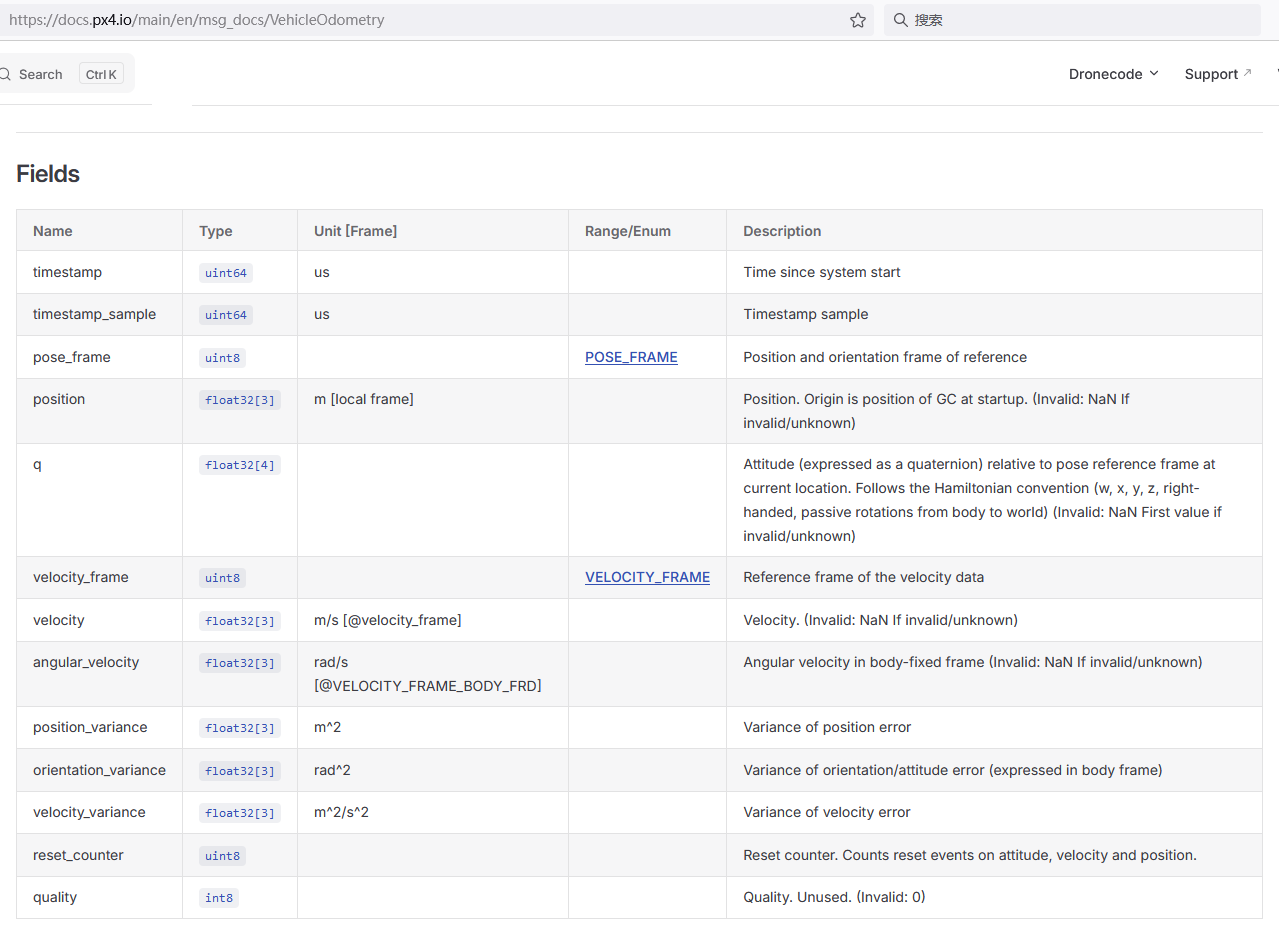
PX4的EKF2模块订阅到vehicle_visual_odometry uORB消息后的取值操作是在EKF2::UpdateExtVisionSample函数里。
PX4-Autopilot\src\modules\ekf2\EKF2.cpp
#if defined(CONFIG_EKF2_EXTERNAL_VISION)
bool EKF2::UpdateExtVisionSample(ekf2_timestamps_s &ekf2_timestamps)
{
	// EKF external vision sample
	bool new_ev_odom = false;

	vehicle_odometry_s ev_odom;

	if (_ev_odom_sub.update(&ev_odom)) {

		extVisionSample ev_data{};
		ev_data.pos.setNaN();
		ev_data.vel.setNaN();
		ev_data.quat.setNaN();

		// check for valid velocity data
		const Vector3f ev_odom_vel(ev_odom.velocity);
		const Vector3f ev_odom_vel_var(ev_odom.velocity_variance);

		bool velocity_frame_valid = false;

		switch (ev_odom.velocity_frame) {
		case vehicle_odometry_s::VELOCITY_FRAME_NED:
			ev_data.vel_frame = VelocityFrame::LOCAL_FRAME_NED;
			velocity_frame_valid = true;
			break;

		case vehicle_odometry_s::VELOCITY_FRAME_FRD:
			ev_data.vel_frame = VelocityFrame::LOCAL_FRAME_FRD;
			velocity_frame_valid = true;
			break;

		case vehicle_odometry_s::VELOCITY_FRAME_BODY_FRD:
			ev_data.vel_frame = VelocityFrame::BODY_FRAME_FRD;
			velocity_frame_valid = true;
			break;
		}

		if (ev_odom_vel.isAllFinite()) {
			if (velocity_frame_valid) {
				ev_data.vel = ev_odom_vel;

				const float evv_noise_var = sq(_param_ekf2_evv_noise.get());

				// velocity measurement error from ev_data or parameters
				if ((_param_ekf2_ev_noise_md.get() == 0) && ev_odom_vel_var.isAllFinite()) {

					ev_data.velocity_var(0) = fmaxf(evv_noise_var, ev_odom_vel_var(0));
					ev_data.velocity_var(1) = fmaxf(evv_noise_var, ev_odom_vel_var(1));
					ev_data.velocity_var(2) = fmaxf(evv_noise_var, ev_odom_vel_var(2));

				} else {
					ev_data.velocity_var.setAll(evv_noise_var);
				}

				new_ev_odom = true;
			}
		}

		// check for valid position data
		const Vector3f ev_odom_pos(ev_odom.position);
		const Vector3f ev_odom_pos_var(ev_odom.position_variance);

		bool position_frame_valid = false;

		switch (ev_odom.pose_frame) {
		case vehicle_odometry_s::POSE_FRAME_NED:
			ev_data.pos_frame = PositionFrame::LOCAL_FRAME_NED;
			position_frame_valid = true;
			break;

		case vehicle_odometry_s::POSE_FRAME_FRD:
			ev_data.pos_frame = PositionFrame::LOCAL_FRAME_FRD;
			position_frame_valid = true;
			break;
		}

		if (ev_odom_pos.isAllFinite()) {
			if (position_frame_valid) {
				ev_data.pos = ev_odom_pos;

				const float evp_noise_var = sq(_param_ekf2_evp_noise.get());

				// position measurement error from ev_data or parameters
				if ((_param_ekf2_ev_noise_md.get() == 0) && ev_odom_pos_var.isAllFinite()) {

					ev_data.position_var(0) = fmaxf(evp_noise_var, ev_odom_pos_var(0));
					ev_data.position_var(1) = fmaxf(evp_noise_var, ev_odom_pos_var(1));
					ev_data.position_var(2) = fmaxf(evp_noise_var, ev_odom_pos_var(2));

				} else {
					ev_data.position_var.setAll(evp_noise_var);
				}

				new_ev_odom = true;
			}
		}

		// check for valid orientation data
		const Quatf ev_odom_q(ev_odom.q);
		const Vector3f ev_odom_q_var(ev_odom.orientation_variance);
		const bool non_zero = (fabsf(ev_odom_q(0)) > 0.f) || (fabsf(ev_odom_q(1)) > 0.f)
				      || (fabsf(ev_odom_q(2)) > 0.f) || (fabsf(ev_odom_q(3)) > 0.f);
		const float eps = 1e-5f;
		const bool no_element_larger_than_one = (fabsf(ev_odom_q(0)) <= 1.f + eps)
							&& (fabsf(ev_odom_q(1)) <= 1.f + eps)
							&& (fabsf(ev_odom_q(2)) <= 1.f + eps)
							&& (fabsf(ev_odom_q(3)) <= 1.f + eps);
		const bool norm_in_tolerance = fabsf(1.f - ev_odom_q.norm()) <= eps;

		const bool orientation_valid = ev_odom_q.isAllFinite() && non_zero && no_element_larger_than_one && norm_in_tolerance;

		if (orientation_valid) {
			ev_data.quat = ev_odom_q;
			ev_data.quat.normalize();

			// orientation measurement error from ev_data or parameters
			const float eva_noise_var = sq(_param_ekf2_eva_noise.get());

			if ((_param_ekf2_ev_noise_md.get() == 0) && ev_odom_q_var.isAllFinite()) {

				ev_data.orientation_var(0) = fmaxf(eva_noise_var, ev_odom_q_var(0));
				ev_data.orientation_var(1) = fmaxf(eva_noise_var, ev_odom_q_var(1));
				ev_data.orientation_var(2) = fmaxf(eva_noise_var, ev_odom_q_var(2));

			} else {
				ev_data.orientation_var.setAll(eva_noise_var);
			}

			new_ev_odom = true;
		}

		// use timestamp from external computer, clocks are synchronized when using MAVROS
		ev_data.time_us = ev_odom.timestamp_sample;
		ev_data.reset_counter = ev_odom.reset_counter;
		ev_data.quality = ev_odom.quality;

		if (new_ev_odom)  {
			_ekf.setExtVisionData(ev_data);
		}

		ekf2_timestamps.visual_odometry_timestamp_rel = (int16_t)((int64_t)ev_odom.timestamp / 100 -
				(int64_t)ekf2_timestamps.timestamp / 100);
	}

	return new_ev_odom;
}
#endif // CONFIG_EKF2_EXTERNAL_VISION
下面对VehicleOdometry.msg里面的一些赋值项做下具体说明
协方差赋值
视觉位姿的协方差,一方面可以在/fmu/in/vehicle_visual_odometry话题里的协方差(准确地讲是方差)进行赋值
另一方面也通过参数 EKF2_EVP_NOISE、EKF2_EVV_NOISE 和 EKF2_EVA_NOISE 进行设置
https://docs.px4.io/main/zh/advanced_config/tuning_the_ecl_ekf#external-vision-system
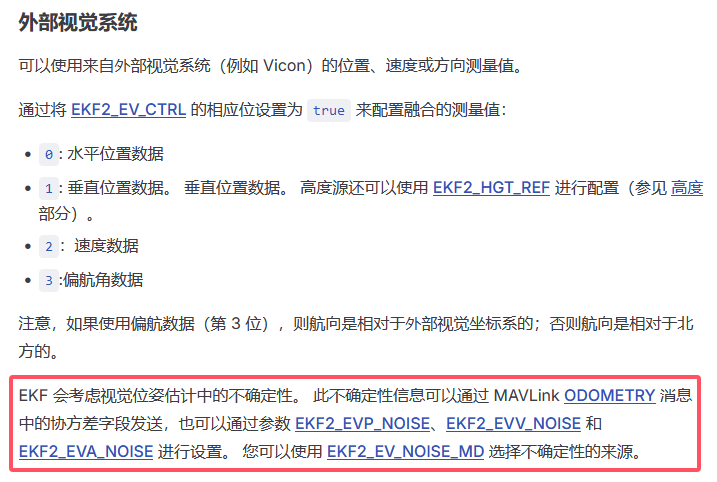
也可以通过EKF2_EV_NOISE_MD参数设置
https://docs.px4.io/main/zh/advanced_config/parameter_reference#EKF2_EV_NOISE_MD
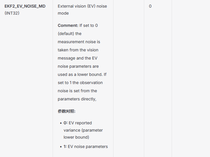
EKF2_EV_NOISE_MD(Noise Mode)用于选择外部视觉(External Vision)观测噪声的来源,即决定 EKF2 在融合 vehicle_visual_odometry 时使用消息中自带的协方差,还是使用参数中设定的固定噪声。
| 值 | 名称 | 含义 |
|---|---|---|
| 0(默认) | EV Pos/Vel/Yaw uses EV noise | 使用消息自带的协方差(来自 VehicleOdometry 的 variance 字段),但参数值会作为下限,也就是协方差始终不会低于EKF2_EVx_NOISE²,防止外部估计器过度自信(R = max(消息方差, 参数²)) |
| 1 | EV Pos/Vel/Yaw uses param noise | 忽略消息里的 position_variance / velocity_variance / orientation_variance,强制使用参数 EKF2_EVP_NOISE、EKF2_EVV_NOISE、EKF2_EVA_NOISE 作为观测噪声 |
当EKF2_EV_NOISE_MD参数设置为0时,效果是 取 消息协方差 与 飞控参数 的较大值:
| 消息字段(VehicleOdometry) | 对应参数 | PX4 实际使用 |
|---|---|---|
position_variance[3] |
EKF2_EVP_NOISE |
max(消息方差, EKF2_EVP_NOISE²) |
velocity_variance[3] |
EKF2_EVV_NOISE |
max(消息方差, EKF2_EVV_NOISE²) |
orientation_variance[3] |
EKF2_EVA_NOISE |
max(消息方差, EKF2_EVA_NOISE²) |
具体规则:
- 消息中协方差为 NaN(未填) → 完全使用参数
EKF2_EVx_NOISE。 - 消息中协方差有效且大于参数² → 使用消息中的协方差(信任发布者给出的较大不确定性)。
- 消息中协方差有效但小于参数² → 使用参数
EKF2_EVx_NOISE(参数作为噪声下限,防止外部估计过度自信)。
也就是说参数并非"覆盖"协方差,而是设定一个"最小噪声"。如果你想完全用话题里的协方差,把这三个飞控参数设小(例如 0.01)即可;如果想忽略话题协方差并强制使用参数,则在发布端把
*_variance字段填 NaN。
对应的代码如下
PX4-Autopilot\src\modules\ekf2\EKF2.cpp
				const float evp_noise_var = sq(_param_ekf2_evp_noise.get());

				// position measurement error from ev_data or parameters
				if ((_param_ekf2_ev_noise_md.get() == 0) && ev_odom_pos_var.isAllFinite()) {

					ev_data.position_var(0) = fmaxf(evp_noise_var, ev_odom_pos_var(0));
					ev_data.position_var(1) = fmaxf(evp_noise_var, ev_odom_pos_var(1));
					ev_data.position_var(2) = fmaxf(evp_noise_var, ev_odom_pos_var(2));

				} else {
					ev_data.position_var.setAll(evp_noise_var);
				}

				const float evv_noise_var = sq(_param_ekf2_evv_noise.get());

				// velocity measurement error from ev_data or parameters
				if ((_param_ekf2_ev_noise_md.get() == 0) && ev_odom_vel_var.isAllFinite()) {

					ev_data.velocity_var(0) = fmaxf(evv_noise_var, ev_odom_vel_var(0));
					ev_data.velocity_var(1) = fmaxf(evv_noise_var, ev_odom_vel_var(1));
					ev_data.velocity_var(2) = fmaxf(evv_noise_var, ev_odom_vel_var(2));

				} else {
					ev_data.velocity_var.setAll(evv_noise_var);
				}

			// orientation measurement error from ev_data or parameters
			const float eva_noise_var = sq(_param_ekf2_eva_noise.get());

			if ((_param_ekf2_ev_noise_md.get() == 0) && ev_odom_q_var.isAllFinite()) {

				ev_data.orientation_var(0) = fmaxf(eva_noise_var, ev_odom_q_var(0));
				ev_data.orientation_var(1) = fmaxf(eva_noise_var, ev_odom_q_var(1));
				ev_data.orientation_var(2) = fmaxf(eva_noise_var, ev_odom_q_var(2));

			} else {
				ev_data.orientation_var.setAll(eva_noise_var);
			}
对于/fmu/in/vehicle_visual_odometry话题里的协方差,因为我们是使用的SLAM位姿里的位置和偏航,所以协方差这里只讨论位置协方差position_variance[]和姿态协方差orientation_variance[](包括偏航协方差orientation_variance[2],同时还会说下roll和pitch的协方差,原因后面有说明)。
首先看位置协方差,位置协方差position_variance[]我们要不要赋值呢,我们分情况讨论,主流SLAM一般分为两种,一种基于优化的,比如vinsfusion,ORBSLAM3,他们一般不输出对应位姿的协方差,像vinsfusion发出的/vins_estimator/odometry话题里面协方差都是0,实际就是没有值。
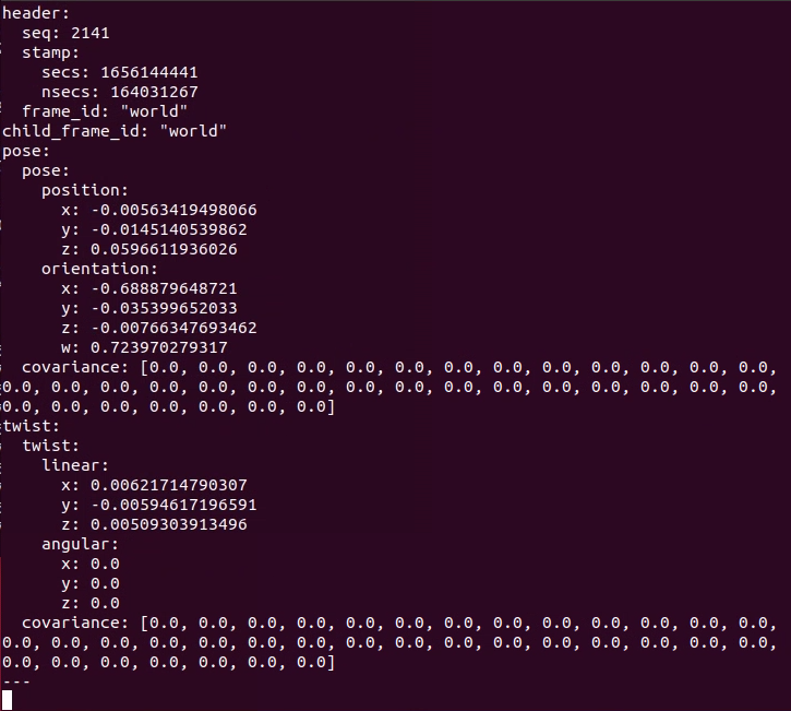
这个时候位姿的协方差只能自己人为估算出一个大概值,可以写在/fmu/in/vehicle_visual_odometry话题的position_variance[]里,也可以设置在EKF2_EVP_NOISE这个飞控参数里,然后设置好EKF2_EV_NOISE_MD。
一种基于滤波的,基于滤波的SLAM,一般计算位姿的同时也会计算对应协方差,因为滤波器的传播与更新过程不仅估计状态,还同步维护其状态协方差矩阵,比如MSCKF,它输出的位姿就带有计算出的协方差,这个时候我们可以用SLAM输出位姿里的协方差给/fmu/in/vehicle_visual_odometry话题的position_variance[]进行赋值,看具体情况是否设置EKF2_EVP_NOISE,然后设置好EKF2_EV_NOISE_MD,看是否完全使用/fmu/in/vehicle_visual_odometry话题的协方差。
MSCKF发出的/firefly_sbx/vio/odom话题(nav_msgs/Odometry.msg类型)里面有协方差
下面这是MSCKF发布位姿话题的函数,里面有对nav_msgs/Odometry.msg类型的位姿话题里的协方差进行赋值
https://github.com/KumarRobotics/msckf_vio/blob/master/src/msckf_vio.cpp
void MsckfVio::publish(const ros::Time& time) {

  // Convert the IMU frame to the body frame.
  const IMUState& imu_state = state_server.imu_state;
  Eigen::Isometry3d T_i_w = Eigen::Isometry3d::Identity();
  T_i_w.linear() = quaternionToRotation(
      imu_state.orientation).transpose();
  T_i_w.translation() = imu_state.position;

  Eigen::Isometry3d T_b_w = IMUState::T_imu_body * T_i_w *
    IMUState::T_imu_body.inverse();
  Eigen::Vector3d body_velocity =
    IMUState::T_imu_body.linear() * imu_state.velocity;

  // Publish tf
  if (publish_tf) {
    tf::Transform T_b_w_tf;
    tf::transformEigenToTF(T_b_w, T_b_w_tf);
    tf_pub.sendTransform(tf::StampedTransform(
          T_b_w_tf, time, fixed_frame_id, child_frame_id));
  }

  // Publish the odometry
  nav_msgs::Odometry odom_msg;
  odom_msg.header.stamp = time;
  odom_msg.header.frame_id = fixed_frame_id;
  odom_msg.child_frame_id = child_frame_id;

  tf::poseEigenToMsg(T_b_w, odom_msg.pose.pose);
  tf::vectorEigenToMsg(body_velocity, odom_msg.twist.twist.linear);

  // Convert the covariance.
  Matrix3d P_oo = state_server.state_cov.block<3, 3>(0, 0);
  Matrix3d P_op = state_server.state_cov.block<3, 3>(0, 12);
  Matrix3d P_po = state_server.state_cov.block<3, 3>(12, 0);
  Matrix3d P_pp = state_server.state_cov.block<3, 3>(12, 12);
  Matrix<double, 6, 6> P_imu_pose = Matrix<double, 6, 6>::Zero();
  P_imu_pose << P_pp, P_po, P_op, P_oo;

  Matrix<double, 6, 6> H_pose = Matrix<double, 6, 6>::Zero();
  H_pose.block<3, 3>(0, 0) = IMUState::T_imu_body.linear();
  H_pose.block<3, 3>(3, 3) = IMUState::T_imu_body.linear();
  Matrix<double, 6, 6> P_body_pose = H_pose *
    P_imu_pose * H_pose.transpose();

  for (int i = 0; i < 6; ++i)
    for (int j = 0; j < 6; ++j)
      odom_msg.pose.covariance[6*i+j] = P_body_pose(i, j);

  // Construct the covariance for the velocity.
  Matrix3d P_imu_vel = state_server.state_cov.block<3, 3>(6, 6);
  Matrix3d H_vel = IMUState::T_imu_body.linear();
  Matrix3d P_body_vel = H_vel * P_imu_vel * H_vel.transpose();
  for (int i = 0; i < 3; ++i)
    for (int j = 0; j < 3; ++j)
      odom_msg.twist.covariance[i*6+j] = P_body_vel(i, j);

  odom_pub.publish(odom_msg);

  // Publish the 3D positions of the features that
  // has been initialized.
  boost::shared_ptr<pcl::PointCloud<pcl::PointXYZ> > feature_msg_ptr(
      new pcl::PointCloud<pcl::PointXYZ>());
  feature_msg_ptr->header.frame_id = fixed_frame_id;
  feature_msg_ptr->height = 1;
  for (const auto& item : map_server) {
    const auto& feature = item.second;
    if (feature.is_initialized) {
      Vector3d feature_position =
        IMUState::T_imu_body.linear() * feature.position;
      feature_msg_ptr->points.push_back(pcl::PointXYZ(
            feature_position(0), feature_position(1), feature_position(2)));
    }
  }
  feature_msg_ptr->width = feature_msg_ptr->points.size();

  feature_pub.publish(feature_msg_ptr);

  return;
}
这是MSCKF位姿话题的终端打印,也可以看到nav_msgs/Odometry.msg类型的位姿话题里的协方差是有值的
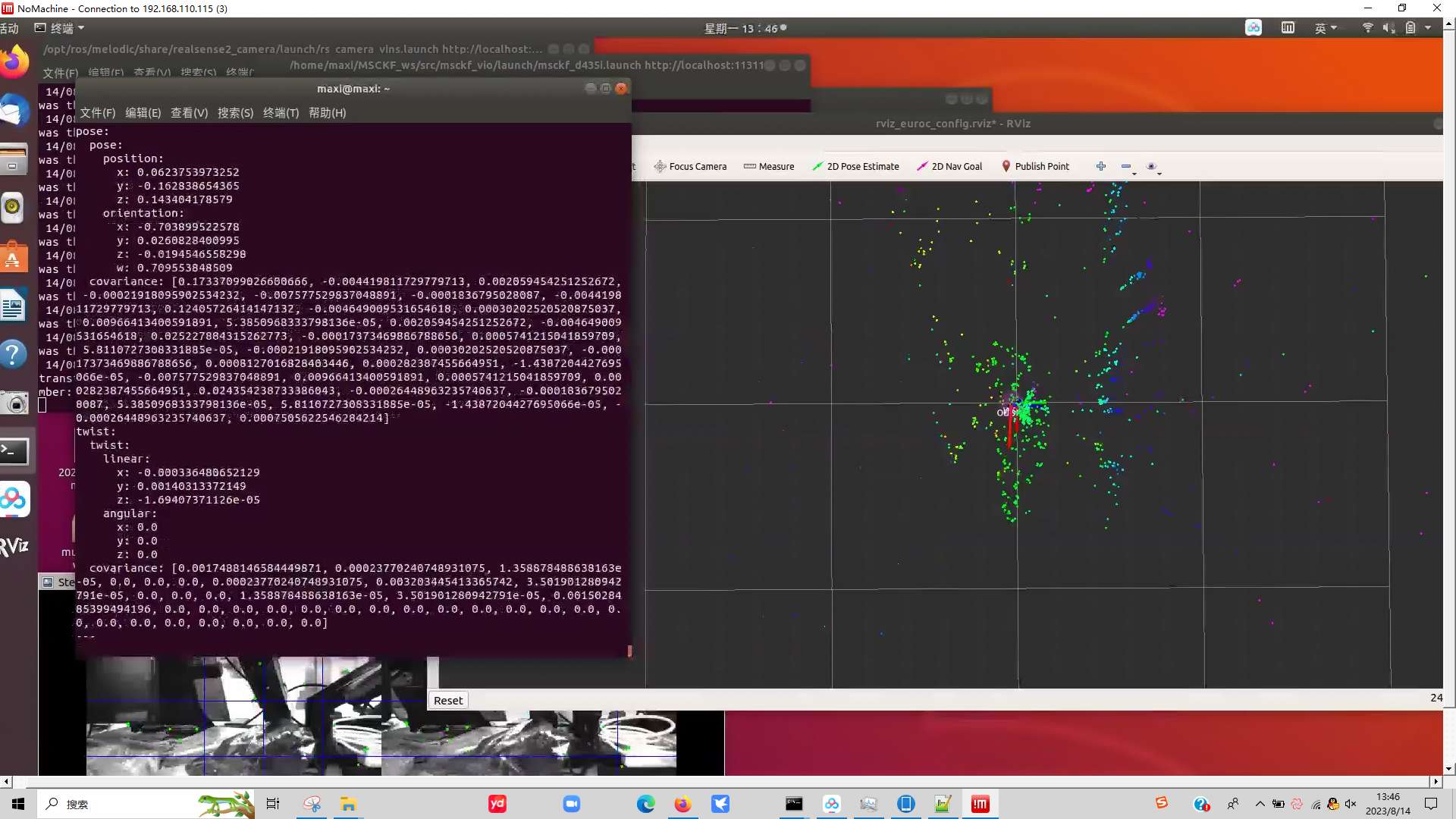
nav_msgs/Odometry.msg 里的协方差和VehicleOdometry.msg里协方差是有些区别的
- nav_msgs/Odometry.msg 协方差结构
nav_msgs/Odometry 包含两个协方差矩阵:
-
pose.covariance(6×6 = 36个元素)- 行主序存储
- 顺序:
[x, y, z, rotation_x, rotation_y, rotation_z] - 表示位置(x,y,z)和姿态(roll, pitch, yaw)的协方差
-
twist.covariance(6×6 = 36个元素)- 行主序存储
- 顺序:
[vx, vy, vz, angular_x, angular_y, angular_z] - 表示线速度和角速度的协方差
- VehicleOdometry.msg 协方差结构
PX4的 VehicleOdometry.msg 使用分离的协方差数组:
position_variance(3个元素):[var_x, var_y, var_z]orientation_variance(3个元素):[var_roll, var_pitch, var_yaw]velocity_variance(3个元素):[var_vx, var_vy, var_vz]
注意:PX4的VehicleOdometry.msg只存储对角线方差,不存储协方差(非对角线元素),nav_msgs/Odometry.msg里才是真正的协方差矩阵。
nav_msgs/Odometry.msg的pose.covariance协方差矩阵结构如下
P=[σx2σxyσxzσxϕσxθσxψσyxσy2σyzσyϕσyθσyψσzxσzyσz2σzϕσzθσzψσϕxσϕyσϕzσϕ2σϕθσϕψσθxσθyσθzσθϕσθ2σθψσψxσψyσψzσψϕσψθσψ2] \mathbf{P} = \begin{bmatrix} \sigma_x^2 & \sigma_{xy} & \sigma_{xz} & \sigma_{x\phi} & \sigma_{x\theta} & \sigma_{x\psi} \\ \sigma_{yx} & \sigma_y^2 & \sigma_{yz} & \sigma_{y\phi} & \sigma_{y\theta} & \sigma_{y\psi} \\ \sigma_{zx} & \sigma_{zy} & \sigma_z^2 & \sigma_{z\phi} & \sigma_{z\theta} & \sigma_{z\psi} \\ \sigma_{\phi x} & \sigma_{\phi y} & \sigma_{\phi z} & \sigma_\phi^2 & \sigma_{\phi\theta} & \sigma_{\phi\psi} \\ \sigma_{\theta x} & \sigma_{\theta y} & \sigma_{\theta z} & \sigma_{\theta\phi} & \sigma_\theta^2 & \sigma_{\theta\psi} \\ \sigma_{\psi x} & \sigma_{\psi y} & \sigma_{\psi z} & \sigma_{\psi\phi} & \sigma_{\psi\theta} & \sigma_\psi^2 \\ \end{bmatrix} P= σx2σyxσzxσϕxσθxσψxσxyσy2σzyσϕyσθyσψyσxzσyzσz2σϕzσθzσψzσxϕσyϕσzϕσϕ2σθϕσψϕσxθσyθσzθσϕθσθ2σψθσxψσyψσzψσϕψσθψσψ2
roll,pitch,yaw对应这三个数学符号 roll → ϕ\phiϕ,pitch → θ\thetaθ,yaw → ψ\psiψ
其中
-
对角线元素(i=ji = ji=j):
- σx2\sigma_x^2σx2:x 位置方差(m2\mathrm{m}^2m2)
- σy2\sigma_y^2σy2:y 位置方差(m2\mathrm{m}^2m2)
- σz2\sigma_z^2σz2:z 位置方差(m2\mathrm{m}^2m2)
- σϕ2\sigma_\phi^2σϕ2:roll 角方差(rad2\mathrm{rad}^2rad2)
- σθ2\sigma_\theta^2σθ2:pitch 角方差(rad2\mathrm{rad}^2rad2)
- σψ2\sigma_\psi^2σψ2:yaw 角方差(rad2\mathrm{rad}^2rad2)
-
非对角线元素:σij\sigma_{ij}σij(i≠ji \ne ji=j),如 σxϕ\sigma_{x\phi}σxϕ、σyψ\sigma_{y\psi}σyψ 等,表示状态 iii 与 jjj 的协方差。
PX4的VehicleOdometry.msg的position_variance[]便存放的σx2\sigma_x^2σx2, σy2\sigma_y^2σy2, σz2\sigma_z^2σz2 ,orientation_variance[]便存放的σϕ2\sigma_\phi^2σϕ2, σθ2\sigma_\theta^2σθ2, σψ2\sigma_\psi^2σψ2 。
两者位置协方差的单位都是m^2,所以可以直接赋值,如下所示,但需要注意坐标系变换,MSCKF输出的位姿的坐标系和/fmu/in/vehicle_visual_odometry话题要求的位姿坐标系不同,所以xyz的协方差对应关系可能也不是下面这样,下面代码只是个赋值演示,实际还要考虑到坐标系变换后xyz的对应关系再进行xyz协方差的赋值,这里的坐标系变换指世界系的变换,不是body系的变换,因为xyz是世界系下的xyz,所以看变换前的世界系的xyz轴和变换后的世界系(PX4的世界系)的xyz轴的对应关系进行赋值,比如变换前世界系的x轴和变换后的px4世界系的y轴是同一方向或者正好180度相反方向,那么就赋值应该是px4_odom.position_variance[1] = ros_odom.pose.covariance[0], 因为方差平方,所以方向相同和方向正好相反,只要是在一条直线上,都是一样赋值的,不用考虑正负。
    nav_msgs::Odometry& ros_odom;
    px4_msgs::VehicleOdometry& px4_odom
    // 1. 位置方差 (提取pose协方差矩阵的对角线元素)
    px4_odom.position_variance[0] = ros_odom.pose.covariance[0];  // x的方差 (索引0,0)
    px4_odom.position_variance[1] = ros_odom.pose.covariance[7];  // y的方差 (索引1,1)
    px4_odom.position_variance[2] = ros_odom.pose.covariance[14]; // z的方差 (索引2,2)
对于姿态协方差,我们先来看下偏航协方差,对于偏航协方差,其实个人实飞经验来讲,没有去专门设置过,感觉影响不大,但还是讲讲,
PX4 融合视觉 yaw 时,yaw 的协方差主要来自 vehicle_visual_odometry.orientation_variance[2],并经过 max(vision_var, ekf2_eva_noise², 0.01²) 的保守处理。飞控参数仅作为兜底/安全上限,不直接决定协方差值。
PX4-Autopilot\src\modules\ekf2\EKF\aid_sources\external_vision\ev_yaw_control.cpp
float obs = getEulerYaw(ev_sample.quat);
float obs_var = math::max(ev_sample.orientation_var(2), sq(_params.ekf2_eva_noise), sq(0.01f));
-
ev_sample.orientation_var(2):来自 vehicle_visual_odometry 消息中的 float32[3] orientation_variance 的第 3 个分量(索引 2),即 yaw(偏航角)的方差(单位 rad²) ,是外部视觉系统(如 VIO、ORB-SLAM、RTAB-Map 等)自身估计的 attitude 误差协方差的对角线元素,表示其对 yaw 精度的置信度。
-
_params.ekf2_eva_noise:PX4 飞控参数 EKF2_EVA_NOISE,是用户可配置的外部视觉 yaw 测量噪声标准差(单位 rad),默认值是0.1 rad,平方后为方差,默认值对应0.01rad²。
-
sq(0.01f):硬编码的最小阈值(0.01 rad ≈ 0.57° 的标准差,即方差 1e⁻⁴ rad²),用于防止方差过小导致滤波器过度信任外部测量而引发数值不稳定。
所以最终的 obs_var 是三者中的最大值
赋值代码如下
px4_odom.orientation_variance[2] = ros_odom.pose.covariance[35];
注意这里不用像xyz协方差一样赋值时要考虑坐标系变换,因为roll、pitch、yaw 的方差都是body系下的,也就是imu坐标系下的(MSCFK里面T_imu_body是单位阵),这是由欧拉角的定义和状态估计的线性化方式决定的。不存在“世界系下的 roll/pitch/yaw 方差”,这种提法在数学和工程上都不成立。不管是MSCFK的imu坐标系的FLU还是FRD,它的z轴都在一个直线上,所以不管坐标系怎么变换,ros_odom.pose.covariance[35]都是对应yaw的协方差。具体说明如下:
1,MSCKF 输出的协方差已是体坐标系(body frame)下的表示
在 msckf_vio.cpp 的 publish() 函数中:
Matrix<double, 6, 6> H_pose = Matrix<double, 6, 6>::Zero();
H_pose.block<3, 3>(0, 0) = IMUState::T_imu_body.linear();
H_pose.block<3, 3>(3, 3) = IMUState::T_imu_body.linear();
Matrix<double, 6, 6> P_body_pose = H_pose * P_imu_pose * H_pose.transpose();
此变换将 IMU 坐标系下的协方差转换到了body系下,实际还是imu坐标系,因为MSCFK里面T_imu_body是单位阵,所以odom_msg.pose.covariance[35](即 (5,5) 元素)表示的就是:在body/imu坐标系下,绕其 z 轴的小角度旋转的方差。
2,PX4 的 VehicleOdometry.orientation_variance[2] 明确定义为:绕body坐标系 z 轴(body-z)的旋转方差(即 yaw 方差)
float32[3] orientation_variance # [rad^2] Variance of orientation/attitude error (expressed in body frame)
L. J. M. L. de Vries, “Error-State Kalman Filtering” (2014) 以及 T. L. Song et al., “On the error-state representation for Kalman filtering” (1999) 明确指出:
The attitude error vector is defined as a small rotation about the current body-frame axes, because the gyroscope measurements are expressed in the body frame and the kinematic equation is naturally expressed in body-frame perturbations.
在 PX4 的 EKF2 实现中(EKF2.cpp、ekf.h),姿态误差协方差(如 _P(6,6), _P(7,7), _P(8,8))对应的是 body 系下的 roll/pitch/yaw 方差,并在协方差传播中通过 rotVelBody 等 body 系量计算雅可比矩阵。
无论body坐标系是 FRD(x 前, y 右, z 下)还是 NED(x 北, y 东, z 下),orientation_variance[2] 始终对应 绕该body坐标系 z 轴的旋转。
PX4 EKF2 在融合时(见 ev_yaw_control.cpp)直接使用 ev_sample.orientation_var(2) 作为 yaw 观测方差,不关心 world 坐标系如何定义,只依赖body坐标系的局部旋转定义。
px4的body系和imu坐标系的关系如下
imu_pos_bodVector3f 类型,用于存储 IMU 在体坐标系(body frame)下的 XYZ 偏移(单位:米)。
PX4-Autopilot\src\modules\ekf2\EKF\common.h
	// XYZ offset of sensors in body axes (m)
	Vector3f imu_pos_body{};                ///< xyz position of IMU in body frame (m)
此代码将参数 EKF2_IMU_POS_X/Y/Z 的值(单位:米)赋给 imu_pos_body
PX4-Autopilot\src\modules\ekf2\EKF2.cpp
	_param_ekf2_imu_pos_x(_params->imu_pos_body(0)),
	_param_ekf2_imu_pos_y(_params->imu_pos_body(1)),
	_param_ekf2_imu_pos_z(_params->imu_pos_body(2)),

		const matrix::Vector3f imu_pos_body(_param_ekf2_imu_pos_x.get(),
						    _param_ekf2_imu_pos_y.get(),
						    _param_ekf2_imu_pos_z.get());
		_ekf.output_predictor().set_imu_offset(imu_pos_body);
EKF2_IMU_POS_X/Y/Z 的值默认都为0,所以默认情况下飞控的body系就是飞控imu坐标系。
当飞控没有放在无人机正中心时,也可以通过设置这三个参数进行调节。
https://docs.px4.io/main/zh/advanced_config/parameter_reference
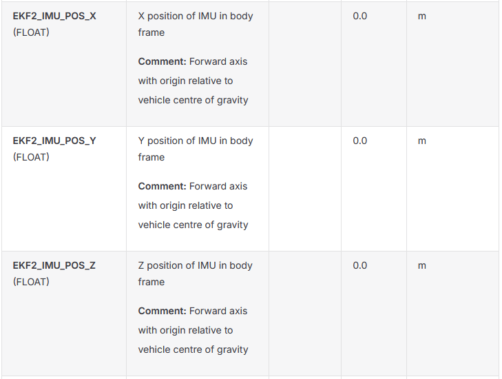
综上可以看出
ros_odom.pose.covariance[35] 对应的是 body frame 下绕 z 轴的小角度旋转方差。
VehicleOdometry.orientation_variance[2] 要求的是 body frame 下绕 z 轴的方差。
而两者的body系都等同于其imu坐标系,如果MSCKF用的飞控imu,飞控的body系是FRD坐标系,MSCKF的body系有两种可能,取决于其订阅的飞控imu话题里的imu数据是什么坐标系,如果飞控imu话题是mavros转发出来的,mavros会把飞控imu数据转成FLU坐标系(不管ROS1还是ROS2都是如此https://github.com/mavlink/mavros/blob/ros2/mavros/src/plugins/imu.cpp),此时MSCKF的body系就是FLU坐标系,如果是通过micro XRCE-DDS发布到ROS端的,则imu数据还是FRD坐标系,此时MSCKF的body系就是FRD坐标系,不管MSCFK的body系是FLU系还是FRD系,此时MSCKF的body系和飞控的body系都是原点重合,Z轴都在一个直线上,所以可以直接用px4_odom.orientation_variance[2] = ros_odom.pose.covariance[35]赋值即可,如果不是一个imu但是两个imu安装方向一致也行,但是这种说法不严谨,理论上应该严格标定,然后改变imu系和body系的变换矩阵使得两者body系重合,但是个人觉得此操作较为繁琐,直接MSCKF用飞控imu即可。
因此,只要body系是FRD/FLU,就直接取 cov[35](即 (5,5))赋值即可,无需根据 world 坐标系映射。
虽然PX4只用了视觉位姿的偏航进行融合,但是对于roll和pitch的协方差,也可以赋值到/fmu/in/vehicle_visual_odometry传给PX4,因为PX4 也使用了 /fmu/in/vehicle_visual_odometry 话题中的 roll 和 pitch 角度的协方差(即 orientation_variance[0] 和 orientation_variance[1]) ,但不是用于融合 roll/pitch 角度本身,而是用于位置协方差的误差传播补偿,具体来说是使用 orientation_variance[0](roll 方差)和 orientation_variance[1](pitch 方差)来增大位置协方差(pos_cov),以反映“姿态不准 → 位置不准”的物理关系。而视觉 yaw 的协方差 orientation_variance[2] 则既用于 yaw 融合(updateEvYaw),又用于位置协方差修正。
PX4-Autopilot\src\modules\ekf2\EKF\aid_sources\external_vision\ev_pos_control.cpp
// Position variance contribution from orientation uncertainty: δp = δθ × p
pos_cov(0, 0) += sq(ev_sample.pos(2)) * ev_sample.orientation_var(1) // pitch
+ sq(ev_sample.pos(1)) * ev_sample.orientation_var(2); // yaw
pos_cov(1, 1) += sq(ev_sample.pos(0)) * ev_sample.orientation_var(2) // yaw
+ sq(ev_sample.pos(2)) * ev_sample.orientation_var(0); // roll
赋值代码如下,而且和yaw的方差赋值时一样,在和上面所说的MSCKF用飞控imu的情况下,不管MSCFK的body系是FLU还是FRD,都是下面这样的赋值,如下图所示,不管是FLU还是FRD,原点重合时,它们的x轴和y轴都是在一条直线上,因为是方差,有平方,不用考虑正负,可以直接赋值。
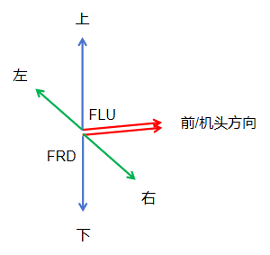
px4_odom.orientation_variance[0] = ros_odom.pose.covariance[21];
px4_odom.orientation_variance[1] = ros_odom.pose.covariance[28];
关于为什么x y z的协方差是世界系下的而姿态的协方差是body系下的说明
位置(x, y, z) 通常是世界系下的状态变量,其协方差描述的是在世界坐标系中位置估计的不确定性,属于主状态(true state)的一部分。
姿态(roll, pitch, yaw 或其等价表示) 在 EKF 中一般不用欧拉角直接作为状态变量(因为奇异性、非线性问题),而是用:
四元数(如 q = [q₀, q₁, q₂, q₃])作为主状态变量(存储在状态向量中),
但协方差中的姿态部分,实际上对应的是姿态误差的局部表示(即误差状态),通常用 3D 小角度误差向量 δθ = [δroll, δpitch, δyaw] (属于 SO(3) 的切空间),姿态属于非线性流形 SO(3),必须通过切空间近似(即小角度误差 δθ)实现线性化,而 δθ 的自然参考系是 body frame(因陀螺仪测量的是 body frame 下的角速度)。所以姿态协方差是定义在 body 系下的。
PX4文档https://docs.px4.io/main/zh/advanced_config/tuning_the_ecl_ekf中说到:为了提高稳定性,实施了“误差状态 (error-state)”表述,这在估计旋转(即 3D 向量,SO(3) 的切空间)的不确定性时尤为重要。
EKF 的状态向量里存的是 x, y, z, v, q, bias, …,但协方差矩阵 P 中与姿态相关的块,不代表 q 的协方差(四元数不能直接算协方差!) ,而是等价于对 小姿态误差 δθ 的协方差建模——这就是“error-state”表述的核心。
四元数(quaternion)不能直接用于计算协方差,根本原因在于:
协方差矩阵是定义在(线性)向量空间上的统计量,而单位四元数构成的是一个非线性流形(3维球面),不是向量空间。
在 EKF 中,协方差传播依赖:
Pk=FkPk−1Fk⊤+Qk P_k = F_k P_{k-1} F_k^\top + Q_k Pk=FkPk−1Fk⊤+Qk
其中 Fk=∂f∂xF_k = \frac{\partial f}{\partial x}Fk=∂x∂f 是状态转移函数的雅可比矩阵。
- 对位置 xxx:f(x)=x+vΔtf(x) = x + v \Delta tf(x)=x+vΔt → F=IF = IF=I,线性;
- 对四元数 qqq:f(q)=q⊗exp(12ωΔt)f(q) = q \otimes \exp\left(\frac{1}{2}\omega \Delta t\right)f(q)=q⊗exp(21ωΔt) → 乘法 + 指数映射,非线性且不可加;
- 雅可比 ∂f∂q\frac{\partial f}{\partial q}∂q∂f 不存在(因为 qqq 不在向量空间);
- 实际中我们只能对 小角度误差 δθ\delta\thetaδθ 求导:
δq≈12[0δθ]⊗q⇒∂δq∂δθ=12[0−δθzδθyδθz0−δθx−δθyδθx0000](近似为 12[δθ]×) \delta q \approx \frac{1}{2} \begin{bmatrix} 0 \\ \delta\theta \end{bmatrix} \otimes q \quad \Rightarrow \quad \frac{\partial \delta q}{\partial \delta\theta} = \frac{1}{2} \begin{bmatrix} 0 & -\delta\theta_z & \delta\theta_y \\ \delta\theta_z & 0 & -\delta\theta_x \\ -\delta\theta_y & \delta\theta_x & 0 \\ 0 & 0 & 0 \end{bmatrix} \text{(近似为 } \frac{1}{2} [\delta\theta]_\times \text{)} δq≈21[0δθ]⊗q⇒∂δθ∂δq=21 0δθz−δθy0−δθz0δθx0δθy−δθx00 (近似为 21[δθ]×)
→ 这才是可线性化的部分。
坐标系赋值
通过/mavros/vision_pose/pose - mavros - VISION_POSITION_ESTIMATE (102) - PX4/src/modules/mavlink/mavlink_receiver.cpp - vehicle_visual_odometry(uORB)
发出的vehicle_visual_odometry uORB消息应该和最后经由uxrce_dds_client 发出的vehicle_visual_odometry uORB消息一样,这样我们可以作为参考,来对VehicleOdometry.msg进行赋值。
ROS1发mavros/vision_pose/pose时没有给坐标系
转成的VISION_POSITION_ESTIMATE (102) mavlink消息里面也没有坐标系
https://mavlink.io/zh/messages/common.html
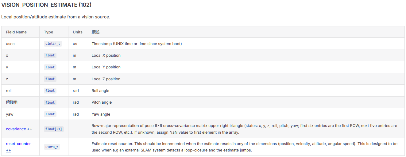
https://github.com/PX4/PX4-Autopilot/blob/main/src/modules/mavlink/mavlink_receiver.h
uORB::Publication<vehicle_odometry_s> _visual_odometry_pub{ORB_ID(vehicle_visual_odometry)};
https://github.com/PX4/PX4-Autopilot/blob/main/src/modules/mavlink/mavlink_receiver.cpp
void
MavlinkReceiver::handle_message_vision_position_estimate(mavlink_message_t *msg)
{
	mavlink_vision_position_estimate_t vpe;
	mavlink_msg_vision_position_estimate_decode(msg, &vpe);

	// fill vehicle_odometry from Mavlink VISION_POSITION_ESTIMATE
	vehicle_odometry_s odom{vehicle_odometry_empty};

	odom.timestamp_sample = _mavlink_timesync.sync_stamp(vpe.usec);

	odom.pose_frame = vehicle_odometry_s::POSE_FRAME_NED;
	odom.position[0] = vpe.x;
	odom.position[1] = vpe.y;
	odom.position[2] = vpe.z;

	const matrix::Quatf q(matrix::Eulerf(vpe.roll, vpe.pitch, vpe.yaw));
	q.copyTo(odom.q);

	// VISION_POSITION_ESTIMATE covariance
	//  Row-major representation of pose 6x6 cross-covariance matrix upper right triangle
	//  (states: x, y, z, roll, pitch, yaw; first six entries are the first ROW, next five entries are the second ROW, etc.).
	//  If unknown, assign NaN value to first element in the array.
	odom.position_variance[0] = vpe.covariance[0];  // X  row 0, col 0
	odom.position_variance[1] = vpe.covariance[6];  // Y  row 1, col 1
	odom.position_variance[2] = vpe.covariance[11]; // Z  row 2, col 2

	odom.orientation_variance[0] = vpe.covariance[15]; // R  row 3, col 3
	odom.orientation_variance[1] = vpe.covariance[18]; // P  row 4, col 4
	odom.orientation_variance[2] = vpe.covariance[20]; // Y  row 5, col 5

	odom.reset_counter = vpe.reset_counter;

	odom.timestamp = hrt_absolute_time();

	_visual_odometry_pub.publish(odom);
}
下面这可以看出给 PX4 发的 VISION_POSITION_ESTIMATE mavlink消息,PX4 默认认为VISION_POSITION_ESTIMATE mavlink消息里的xyz和四元数的就是 NED 坐标,所以自动进行下面赋值
odom.pose_frame = vehicle_odometry_s::POSE_FRAME_NED;
对于速度坐标系,因为我们一般不把SLAM位姿中的速度发给PX4做融合,这里不作讨论。如果确实有需要的,SLAM位姿中的速度一般是和位置一个坐标系,所以一般赋值为velocity_frame = px4_msgs::msg::VehicleOdometry::VELOCITY_FRAME_NED。
时间戳赋值
VehicleOdometry.msg里面有两个时间变量的赋值,timestamp和timestamp_sample。
timestamp_sample 表示 这帧视觉里程计数据对应的实际采样时刻,也就是相机图像产生所对应的时间
timestamp 是 PX4 系统启动以来的时间,单位微秒,通常表示这条 uORB 消息被发布/送入 PX4 的时间
举个例子
假设:
相机在 t = 100.000 s 拍到图像;
SLAM 算法处理用了 30 ms;
ROS 2 发布时已经是 t = 100.030 s。
那么理想情况下:
msg.timestamp_sample = 100000000;  // 图像采样时间,us
msg.timestamp        = 100030000;  // 消息发布时间,us
如果我们没有准确的采样时间,那就把timestamp赋值给timestamp_sample这么来处理,虽然略微不太严谨,但这也是不知道实际准确采用时间的情况下最好的处理方式了,从实际飞行角度,这么处理对于一般简单的飞行影响不大(当然SLAM的处理耗时也不能太大):
msg.timestamp_sample = msg.timestamp;
vehicle_visual_odometry消息被EKF2模块订阅后,两个时间戳起的作用也不一样。
- timestamp仅用于性能统计:_last_event_vision_data_received、丢消息计数 (_msg_missed_odometry_perf)、延迟分析;不参与状态估计。
- timestamp_sample是EKF融合所用的时间戳。它代表测量真正对应的物理时刻,用于把测量插入 EKF 的延迟时间缓冲区(time-horizon buffer)中正确的位置。它会减去 EKF2_EV_DELAY*1000 后作为 extVisionSample::time_us 存入缓冲,之后在 ev_control.cpp 等里通过 pop_first_older_than(_time_delayed_us, …) 提取并与 IMU 等其它传感器在同一延迟时间轴上做融合。
然后我们看看mavlink_receiver.cpp收到VISION_POSITION_ESTIMATE mavlink消息然后发出vehicle_visual_odometry uORB消息时是如何对vehicle_visual_odometry的时间戳赋值的,VISION_POSITION_ESTIMATE mavlink消息里面有时间戳选项。可以是UTC时间或者PX4启动的时间。
https://mavlink.io/en/messages/common.html#VISION_POSITION_ESTIMATE
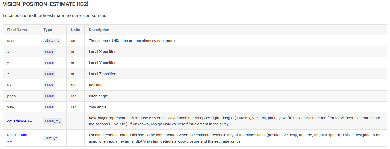
我们发布/mavros/vision_pose/pose时也会对其时间戳赋值
        geometry_msgs::PoseStamped vision;

        vision.pose.position.x = pos_drone_vins[0];
        vision.pose.position.y = pos_drone_vins[1];
        vision.pose.position.z = pos_drone_vins[2];

        vision.pose.orientation.x = q_vins.x();
        vision.pose.orientation.y = q_vins.y();
        vision.pose.orientation.z = q_vins.z();
        vision.pose.orientation.w = q_vins.w();


        vision.header.stamp = ros::Time::now();
        vision_pub.publish(vision);
但实际在mavlink_receiver.cpp handle_message_vision_position_estimate函数的处理里,并不直接使用VISION_POSITION_ESTIMATE 里的时间戳,如下所示
在PX4-Autopilot/src/modules/mavlink/mavlink_receiver.cpp handle_message_vision_position_estimate函数中
	odom.timestamp_sample = _mavlink_timesync.sync_stamp(vpe.usec);
	odom.timestamp = hrt_absolute_time();
首先看下 _mavlink_timesync.sync_stamp(vpe.usec)
vpe.usec 来自 MAVLink 消息:
mavlink_vision_position_estimate_t vpe;
其中 vpe.usec 是 VISION_POSITION_ESTIMATE 消息里的时间戳,一般由板载计算机发送,它一般是Unix时间(从1970年1月1日00:00:00 UTC起经过的秒数)。
sync_stamp函数的功能是若时间同步已收敛,则将输入的时间戳 usec(微秒)加上估计的时钟偏移 _time_offset,返回校准后的时间戳;否则返回当前PX4 系统本地高精度实时时间 hrt_absolute_time()。
https://github.com/PX4/PX4-Autopilot/blob/main/src/lib/timesync/Timesync.cpp
uint64_t Timesync::sync_stamp(uint64_t usec)
{
	// Only return synchronised stamp if we have converged to a good value
	if (sync_converged()) {
		return usec + (int64_t)_time_offset;

	} else {
		return hrt_absolute_time();
	}
}
sync_converged函数定义如下
它功能是:
判断时间同步是否已完成“收敛”:当已交换的同步报文数量 _sequence 达到或超过预设阈值 CONVERGENCE_WINDOW = 500 时,返回 true(表示算法已稳定,偏移估计可信);否则返回 false。
https://github.com/PX4/PX4-Autopilot/blob/main/src/lib/timesync/Timesync.hpp#L113
// Filter gain scheduling
//
// The filter interpolates between the INITIAL and FINAL gains while the number of
// exhanged timesync packets is less than CONVERGENCE_WINDOW. A lower value will
// allow the timesync to converge faster, but with potentially less accurate initial
// offset and skew estimates.
static constexpr uint32_t CONVERGENCE_WINDOW = 500;

	/**
	 * Return true if the timesync algorithm converged to a good estimate,
	 * return false otherwise
	 */
	bool sync_converged() const { return _sequence >= CONVERGENCE_WINDOW; }
为什么sync_stamp函数里在时间同步收敛后要使用usec + (int64_t)_time_offset而不是hrt_absolute_time()呢,因为usec + (int64_t)_time_offset会更接近真实的采样时间(PX4基准下),hrt_absolute_time()是得到的消息送到PX4内部时的PX4基准下的时间,两者有可能相差了比如几十毫秒,如果usec 就是对应的视觉SLAM的相机当时的采样时间(UTC),那么usec + (int64_t)_time_offset和hrt_absolute_time()之间会相差一个SLAM的处理时间,和传输到PX4的传输时间,所以用usec + (int64_t)_time_offset体现的就是视觉SLAM的相机当时的采样时间(PX4基准下),赋值给timestamp_sample ,timestamp 呢就是直接赋值的hrt_absolute_time(),表示这条消息被送入 PX4 的时间。
它得到的是:外部视觉数据采样时刻,转换到 PX4 本机时间基准下的时间戳,单位是微秒。
也就是 vehicle_odometry.timestamp_sample。
然后说下hrt_absolute_time()
odom.timestamp = hrt_absolute_time();
hrt_absolute_time() 是 PX4 中一个关键的高精度时间获取函数,用于获取高分辨率定时器(High Resolution Timer, HRT)的绝对时间戳,单位为微秒(µs),即从系统启动(或定时器复位)开始经过的微秒数。
它得到的是:PX4 飞控当前本机时间,单位是微秒。
通常可以理解为:PX4 系统启动以来经过的时间,单位 us
例如 PX4 启动了 120 秒,那么:
hrt_absolute_time()
大约可能返回:120000000
单位是微秒。
它不是 UTC 时间,是 PX4 内部的高精度单调时间。
这里说明一下所有 uORB 消息的时间戳均以 PX4 本机启动时间为基准,EKF2 模块正是订阅这些统一时间基准的 uORB 消息进行状态融合,传统飞控它没有板载计算机也不联网,按照PX4启动时间来作为时间戳很合理,各个传感器都是上电后才启动,所以SLAM位姿要进入EKF2模块融合相应uORB消息的时间戳也需要是以PX4启动时间为基准的,不然EKF融合会有问题。
PX4和ROS2的时间同步
PX4-Autopilot\src\modules\uxrce_dds_client\module.yaml
        UXRCE_DDS_SYNCT:
            description:
                short: Enable uXRCE-DDS timestamp synchronization
                long: When enabled, uxrce_dds_client will synchronize the timestamps
                    of the incoming and outgoing messages measuring the offset
                    between the Agent OS time and the PX4 time.
            type: boolean
            category: System
            reboot_required: true
            default: 1
UXRCE_DDS_SYNCT 参数(boolean 类型)用于启用 uXRCE-DDS 时间戳同步功能。其作用是:当该参数启用(默认为 1,即启用)时,uxrce_dds_client 模块会在与 uXRCE-DDS Agent 建立会话后,测量并维护 PX4 系统时间(hrt_absolute_time())与 Agent 系统 UTC 时间之间的偏移量(time offset) ,从而对所有通过 DDS 传输的传入/传出消息的时间戳进行校正,使其统一到 PX4 的高精度时间基准上(通常为 hrt_absolute_time(),即硬件相关时间,单位为纳秒)。
dds_topic.h.em(https://github.com/PX4/PX4-Autopilot/blob/main/src/modules/uxrce_dds_client/dds_topics.h.em) 中通过 on_topic_update 回调函数,对所有订阅的 DDS 消息(包括 /fmu/in/vehicle_visual_odometry)的时间戳,统一使用 session->time_offset / 1000(纳秒转微秒)作为偏移量进行校正,确保进入 uORB 的时间戳是 PX4 的基准时间(hrt_abstime 单位:微秒)。
该机制是 PX4 与 DDS/ROS 2 时间同步的核心设计,避免因时钟不同步导致的控制延迟或滤波发散问题.
PX4 对传入的 /fmu/in/vehicle_visual_odometry 时间戳的转换,完全由 dds_topic.h.em 模板生成的 on_topic_update 回调 + ucdr_deserialize_vehicle_odometry(…, time_offset_us) 函数 实现:
- 从 dds_topics.yaml 确认其为订阅项;
- 模板生成 RcvTopicsPubs 中的 vehicle_visual_odometry_pub;
- 在 DDS 消息到达时,调用 ucdr_deserialize_vehicle_odometry(…, time_offset_us);
- 该函数将 DDS 消息中的 timestamp(Agent UTC 时间,μs)减去 time_offset_us ,得到 PX4 的 hrt_absolute_time() 对应的微秒值;
- 写入 uORB 消息的 timestamp 字段。
ucdr_deserialize_vehicle_odometry(…, time_offset_us) 实现时间戳校正
该函数由 ucdr 工具链自动生成(基于 vehicle_odometry.msg IDL),其内部逻辑(典型实现)如下:
bool ucdr_deserialize_vehicle_odometry(ucdrBuffer& buf, vehicle_odometry_s& msg, int64_t time_offset_us) {
    // ... 其他字段反序列化 ...
    uint64_t agent_timestamp_us;
    ucdr_deserialize_uint64_t(buf, &agent_timestamp_us);  // 从 DDS 消息中读取 timestamp(Agent 的 UTC 时间,单位 μs)

    // 校正:Agent 时间 = PX4 hrt 时间 + time_offset_us
    // → PX4 hrt 时间 = Agent 时间 - time_offset_us
    int64_t px4_hrt_us = (int64_t)agent_timestamp_us - time_offset_us;

    // 写入 uORB 消息(uORB timestamp 单位为 μs,但语义是 hrt_absolute_time() 的微秒值)
    msg.timestamp = px4_hrt_us;  // 直接赋值,即已转换为 PX4 基准时间
    // ... 其余字段 ...
}
所以/fmu/in/vehicle_visual_odometry的timestamp和timestamp_sample进行赋值时,可以直接用SLAM位姿话题的时间戳,或者直接取当时ROS的时间戳(可能略微不太严谨,但是影响不大),uxrce_dds_client 模块会自动把时间戳转为PX4的基准时间,不用自己在ROS端手动去转。
reset_counter
reset_counter 用于计数SLAM位姿里 “姿态、速度、位置” 状态被重置(reset)或者说跳变的次数,例如因为回环发生位姿跳变,因为短暂跟丢后又重定位成功发生的位姿跳变等等。
reset_counter赋值方式是:
外部节点(如 vins-fusion 或 ORBSLAM3 的 ROS 节点)在每次发生重置时,主动递增该字段值(通常从 0 开始,每次重置加 1),默认初始化为 0;
PX4 不会自动修改或递增此字段;它仅接收并使用该值(例如用于判断是否需重置本地 EKF 的状态),PX4 的 EKF 2 在接收 VehicleOdometry 时,会检查 reset_counter 是否变化,以决定是否同步重置内部状态;
这对于基于SLAM飞无人机而言也是个较为实用的功能,也是原先/mavros/vision_pose/pose所实现不了的。这样允许我们在基于SLAM飞无人机时运行视觉SLAM系统在回环检测或重定位后发送位姿跳变。
如果SLAM位姿出现大跳变而reset_counter 无变化,EKF 会因为新息(innovation)过大而触发门限拒绝(innovation gate),认为测量(SLAM位姿)无效,EKF会拒绝融合,暂时退回为纯IMU估计,时间长了无人机的位姿就可能开始飘了。出现了大跳变且reset_counter + 1,则PX4会将 EKF 的状态(_state)直接重置为外部输入的新位姿,local position(vehicle_local_position uorb消息) 的 x, y, z 和偏航 也会立即跳变到新值,控制环也会对应做出一些调整。
PX4仓库的issue里面也有一些对reset_counter参数的讨论可以看看
https://github.com/PX4/PX4-Autopilot/issues/11970
这里首先解释下观测新息和新息方差
观测新息(Innovation)
-
定义:实际观测量 与 基于当前状态预测的观测量 之间的差值
y=z−h(x^) \mathbf{y} = \mathbf{z} - h(\hat{\mathbf{x}}) y=z−h(x^)
其中:- z\mathbf{z}z:传感器实际观测值(如视觉给出的位置);
- h(x^)h(\hat{\mathbf{x}})h(x^):由当前状态估计 x^\hat{\mathbf{x}}x^ 经过观测模型 h(⋅)h(\cdot)h(⋅) 预测出的观测值;
- y\mathbf{y}y:即“新息”,单位与观测量一致(例如:米、m/s、rad 等)。
-
物理意义:若新息接近 0,说明预测与实际观测一致,估计可靠;若新息过大,可能表示:
- 传感器故障/异常;
- 模型不匹配(如运动假设错误);
- 状态估计发散;
- 外部环境突变(如视觉突然丢失特征)。
新息方差(Innovation Variance)
-
定义:新息的理论协方差(不确定性),记作 S=HPH⊤+RS = H P H^\top + RS=HPH⊤+R
其中:- HHH:观测雅可比(Hessian),即 ∂h/∂x\partial h / \partial \mathbf{x}∂h/∂x;
- PPP:状态协方差矩阵;
- RRR:传感器观测噪声协方差;
- SSS 是一个标量(1D)或对角阵(2D/3D),单位为观测量的平方(如 m²、(m/s)²)。
-
物理意义:反映“预期的新息波动范围”。新息是否“合理”,需与新息方差比较(见下面创新检验比)。
创新检验比(Innovation Test Ratio)
- 定义:
γ=∣y∣S \gamma = \frac{|\mathbf{y}|}{\sqrt{S}} γ=S∣y∣
若 γ>gate\gamma > \text{gate}γ>gate(如EKF2_EVP_GATE = 3.0,各观测类型的检查标准差数由对应的 EKF2_*_GATE 参数控制),则认为该观测超出 3σ 范围,拒绝融合(防止污染状态估计),这也叫统计置信度检查,统计置信度检查”的本质是用卡方/高斯假设检验思想,判断观测是否在预期置信区间内。
计算新息,计算新息方差,计算检验比在调用的updateAidSourceStatus函数内部
PX4-Autopilot\src\modules\ekf2\EKF\aid_sources\external_vision\ev_pos_control.cpp
	const Vector2f measurement_var{
		math::max(pos_cov(0, 0), sq(_params.ekf2_evp_noise), sq(0.01f)),
		math::max(pos_cov(1, 1), sq(_params.ekf2_evp_noise), sq(0.01f))
	};

	const Vector2f position = measurement - _ev_pos_b_est.getBias();
	const Vector2f pos_obs_var = measurement_var + _ev_pos_b_est.getBiasVar();

	updateAidSourceStatus(aid_src,
			      ev_sample.time_us,                                      // sample timestamp
			      position,                                               // observation
			      pos_obs_var,                                            // observation variance
			      position_estimate - position,                           // innovation
			      Vector2f(getStateVariance<State::pos>()) + pos_obs_var, // innovation variance
			      math::max(_params.ekf2_evp_gate, 1.f));             // innovation gate
其中
	const Vector2f measurement_var{
		math::max(pos_cov(0, 0), sq(_params.ekf2_evp_noise), sq(0.01f)),
		math::max(pos_cov(1, 1), sq(_params.ekf2_evp_noise), sq(0.01f))
	};
- pos_cov(i, i):来自外部视觉系统的协方差(如通过/fmu/in/vehicle_visual_odometry传入的协方差);
- _params.ekf2_evp_noise:配置的最小观测噪声标准差(EKF2_EV_P_NOISE 参数),防止协方差过小导致过度信任;
- 0.01f:硬性下限(1 cm),防止数值不稳定。
其中position_estimate - position是计算新息Vector2f(getStateVariance<State::pos>()) + pos_obs_var是计算新息方差
PX4-Autopilot\src\modules\ekf2\EKF\ekf_helper.cpp
void Ekf::updateAidSourceStatus(estimator_aid_source1d_s &status, const uint64_t ×tamp_sample,
const float &observation, const float &observation_variance,
const float &innovation, const float &innovation_variance,
float innovation_gate) const
{
bool innovation_rejected = false;
//计算检验比
const float test_ratio = sq(innovation) / (sq(innovation_gate) * innovation_variance);
if ((status.timestamp_sample > 0) && (timestamp_sample > status.timestamp_sample)) {
const float dt_s = math::constrain((timestamp_sample - status.timestamp_sample) * 1e-6f, 0.001f, 1.f);
static constexpr float tau = 0.5f;
const float alpha = math::constrain(dt_s / (dt_s + tau), 0.f, 1.f);
// test_ratio_filtered
if (PX4_ISFINITE(status.test_ratio_filtered)) {
status.test_ratio_filtered += alpha * (matrix::sign(innovation) * test_ratio - status.test_ratio_filtered);
} else {
// otherwise, init the filtered test ratio
status.test_ratio_filtered = test_ratio;
}
// innovation_filtered
if (PX4_ISFINITE(status.innovation_filtered)) {
status.innovation_filtered += alpha * (innovation - status.innovation_filtered);
} else {
// otherwise, init the filtered innovation
status.innovation_filtered = innovation;
}
// limit extremes in filtered values
static constexpr float kNormalizedInnovationLimit = 2.f;
static constexpr float kTestRatioLimit = sq(kNormalizedInnovationLimit);
if (test_ratio > kTestRatioLimit) {
status.test_ratio_filtered = math::constrain(status.test_ratio_filtered, -kTestRatioLimit, kTestRatioLimit);
const float innov_limit = kNormalizedInnovationLimit * innovation_gate * sqrtf(innovation_variance);
status.innovation_filtered = math::constrain(status.innovation_filtered, -innov_limit, innov_limit);
}
} else {
// invalid timestamp_sample, reset
status.test_ratio_filtered = test_ratio;
status.innovation_filtered = innovation;
}
status.test_ratio = test_ratio;
status.observation = observation;
status.observation_variance = observation_variance;
status.innovation = innovation;
status.innovation_variance = innovation_variance;
	if ((test_ratio > 1.f)
	    || !PX4_ISFINITE(test_ratio)
	    || !PX4_ISFINITE(status.innovation)
	    || !PX4_ISFINITE(status.innovation_variance)
	   ) {
		innovation_rejected = true;
	}
status.timestamp_sample = timestamp_sample;
// if any of the innovations are rejected, then the overall innovation is rejected
status.innovation_rejected = innovation_rejected;
// reset
status.fused = false;
}
计算检验比是在上面函数中的这一句
const float test_ratio = sq(innovation) / (sq(innovation_gate) * innovation_variance);
对应的公式是 KaTeX parse error: Expected 'EOF', got '_' at position 11: \text{test_̲ratio} = \left(…
统计置信度检查是在
if ((test_ratio > 1.f)
|| !PX4_ISFINITE(test_ratio)
|| !PX4_ISFINITE(status.innovation)
|| !PX4_ISFINITE(status.innovation_variance)
) {
innovation_rejected = true;
}
其中:
gate=innovation_gate(如EKF2_EVP_GATE = 3.0),是标准差倍数门限(sigma gate)- 所以:
KaTeX parse error: Expected 'EOF', got '_' at position 11: \text{test_̲ratio} > 1 \qua…
为什么这里阈值是 1.0?因为 test_ratio 已是 (γ/gate)2(\gamma / \text{gate})^2(γ/gate)2,所以 若 gate = 3,则 test_ratio > 1 ⇔ $ \gamma > 3 $ 。
innovation_rejected = true;
innovation_rejected 为 true,会导致后续融合被跳过(跳过的是当前一轮EKF更新里的融合,下一次视觉位姿到了会重新计算检查创新检验比)。
在Ekf::fuseHorizontalPosition() Ekf::fuseVerticalPosition() Ekf::fuseHorizontalVelocity() Ekf::fuseVelocity() Ekf::fuseBodyFrameVelocity() Ekf::fuseYaw()这些函数里都基本一开头就对innovation_rejected进行检查,innovation_rejected为false才会执行融合,innovation_rejected = false,表示新息通过了统计置信度检验,可被滤波器安全采用,用于状态更新innovation_rejected为true是不执行相应融合函数的。
以Ekf::fuseHorizontalPosition()为例,innovation_rejected 为 true 后。
跳过状态融合:fuseDirectStateMeasurement() 不会被调用 → 水平位置(x, y)不会更新;
设置融合标志为 false:aid_src.fused = false;
不更新时间戳:aid_src.time_last_fuse 和 _time_last_hor_pos_fuse 保持不变;
返回 false :函数返回 aid_src.fused,即 false。
fuseHorizontalPosition函数里会进行innovation_rejected的检查,innovation_rejected如果为true(在上面updateAidSourceStatus函数中赋值),会跳过融合(跳过的是当前一轮EKF更新里的融合,下一次视觉位姿到了会重新计算检查创新检验比)。
PX4-Autopilot\src\modules\ekf2\EKF\position_fusion.cpp
bool Ekf::fuseHorizontalPosition(estimator_aid_source2d_s &aid_src)
{
	// x & y
	if (!aid_src.innovation_rejected) {
		for (unsigned i = 0; i < 2; i++) {
			fuseDirectStateMeasurement(aid_src.innovation[i], aid_src.innovation_variance[i], aid_src.observation_variance[i],
						   State::pos.idx + i);
		}

		aid_src.fused = true;
		aid_src.time_last_fuse = _time_delayed_us;

		_time_last_hor_pos_fuse = _time_delayed_us;

	} else {
		aid_src.fused = false;
	}

	return aid_src.fused;
}
后续的影响是
有两种情况,
第一种情况,在1秒钟内,有新到来的视觉位姿使得新息统计置信度检查通过,EKF重新开始融合视觉位姿。
第二种情况,如果持续达一秒钟,视觉位姿的新息都被拒绝,
由于 fuseHorizontalPosition() 返回 false,且 aid_src.time_last_fuse 未更新,会导致:
_time_last_hor_pos_fuse 长期未刷新;
后续检测 isTimedOut(_time_last_hor_pos_fuse, _params.no_aid_timeout_max) 可能返回 true,也就是拒绝融合的时长达到一秒钟,no_aid_timeout_max的定义如下 ;
PX4-Autopilot\src\modules\ekf2\EKF\common.h
const unsigned no_aid_timeout_max{1'000'000}; ///< maximum lapsed time from last fusion of a measurement that constrains horizontal velocity drift before the EKF will determine that the sensor is no longer contributing to aiding (uSec)
进而触发 融合失败重置逻辑(见下面 updateEvPosFusion 函数中的if(is_fusion_failing)分支),最终可能调用 resetHorizontalPositionTo()。
也就是px4文档这里所说的 如果时间足够长,使得 EKF 尝试重置状态以使用传感器观测数据。
https://docs.px4.io/main/zh/advanced_config/tuning_the_ecl_ekf
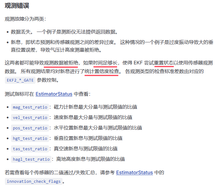
因为位姿跳变导致innovation_rejected = true,即新息被拒绝,后续的情况可以粗略分为两种,一种是这种跳变是冲激信号类型的,短时间内跳出去又跳回来了,这种跳回来后可能新息的统计置信度检查通过了又继续融合了。一种是阶跃信号类型的跳变,常见的比如SLAM发生回环或者重定位了,甚至SLAM位姿发散了,这种跳变出去就不会跳回来了,那很可能就是导致较长时间的新息被拒绝,超出时间阈值(本文代码版本对应阈值是1秒),然后就会触发reset,而且拒绝融合后,无人机实际就是定高模式在飞了,水平位置会飘得厉害,飞控内部水平位置靠IMU积分,对于阶跃信号类跳变,一般很难短时间内像冲激信号类跳变那样再跳变回来,使得新息的统计置信度检查通过然后重新融合,随着飞机飘得越来越厉害,一般只会让视觉位姿和EKF估计位姿新息越来越大,新息基本不可能自然地通过统计置信度检查重新进行融合,最后只能走到reset的路上。
说明:当某一帧视觉观测的创新检验不通过时,在这一轮 EKF 更新中,滤波器只会执行 IMU 预测步骤:依靠 IMU 的角速度和加速度积分来更新状态和协方差,也就是进入纯惯性航位推算模式,暂时脱离视觉辅助。
下两幅日志截图展现的就是冲激信号类跳变和阶跃信号类跳变。
是否发生了innovation_rejected = true,可以查看estimator_status_flags_0.reject_hor_pos,estimator_status_flags_0.reject_hor_pos是EKF状态标志位中的一个位标志(bit flag),表示水平位置(horizontal position)观测值是否被拒绝(rejected),是bool类型,值为0或者1,为1时表示水平位置观测值被拒绝,也就是发生了innovation_rejected = true。estimator_status_flags_0.reject_hor_pos是图片中的蓝线。
图片中的红线是EKF估计出的local position的x,绿线是视觉位姿(已转到飞控坐标系下)中的x。
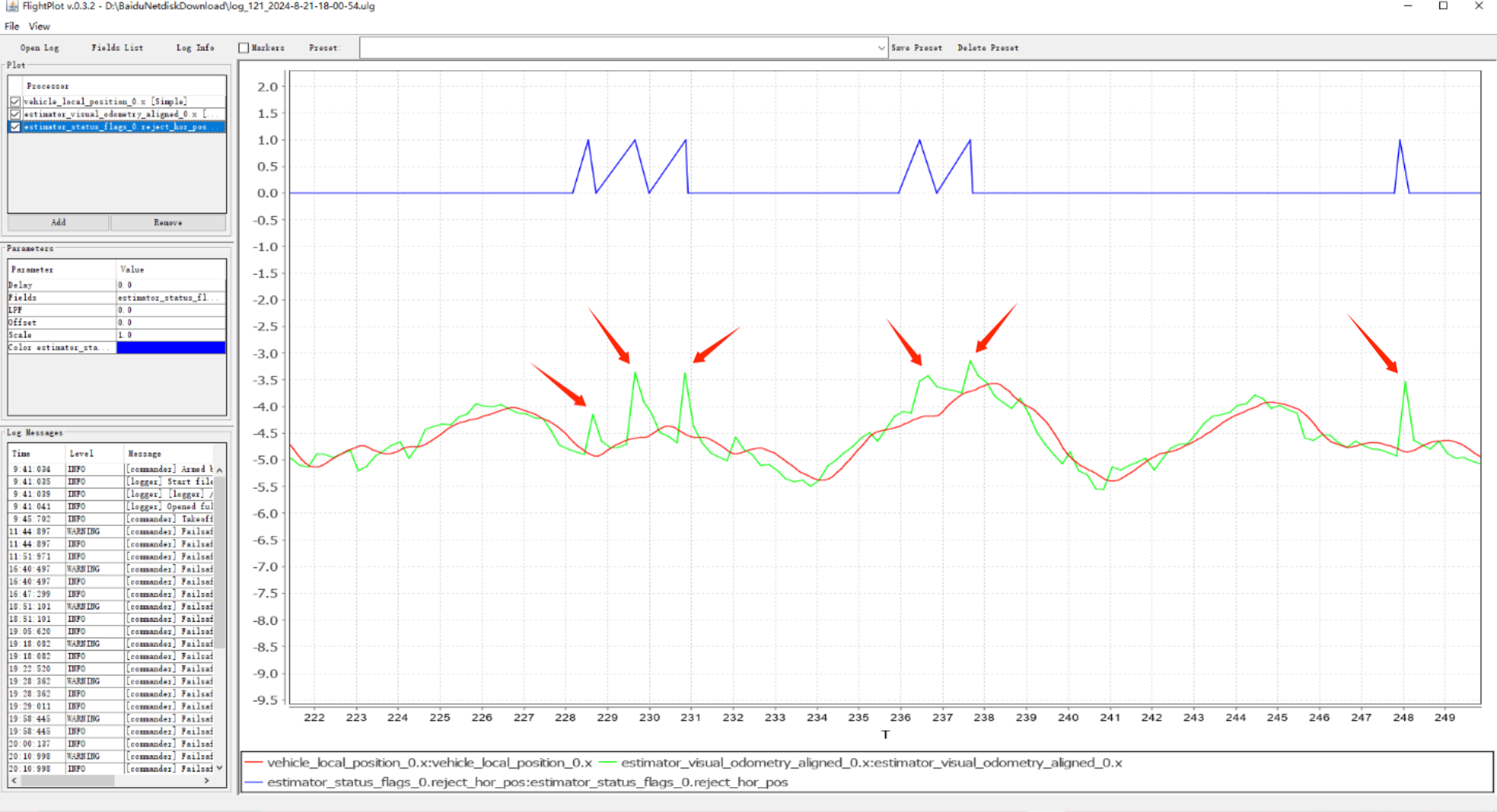
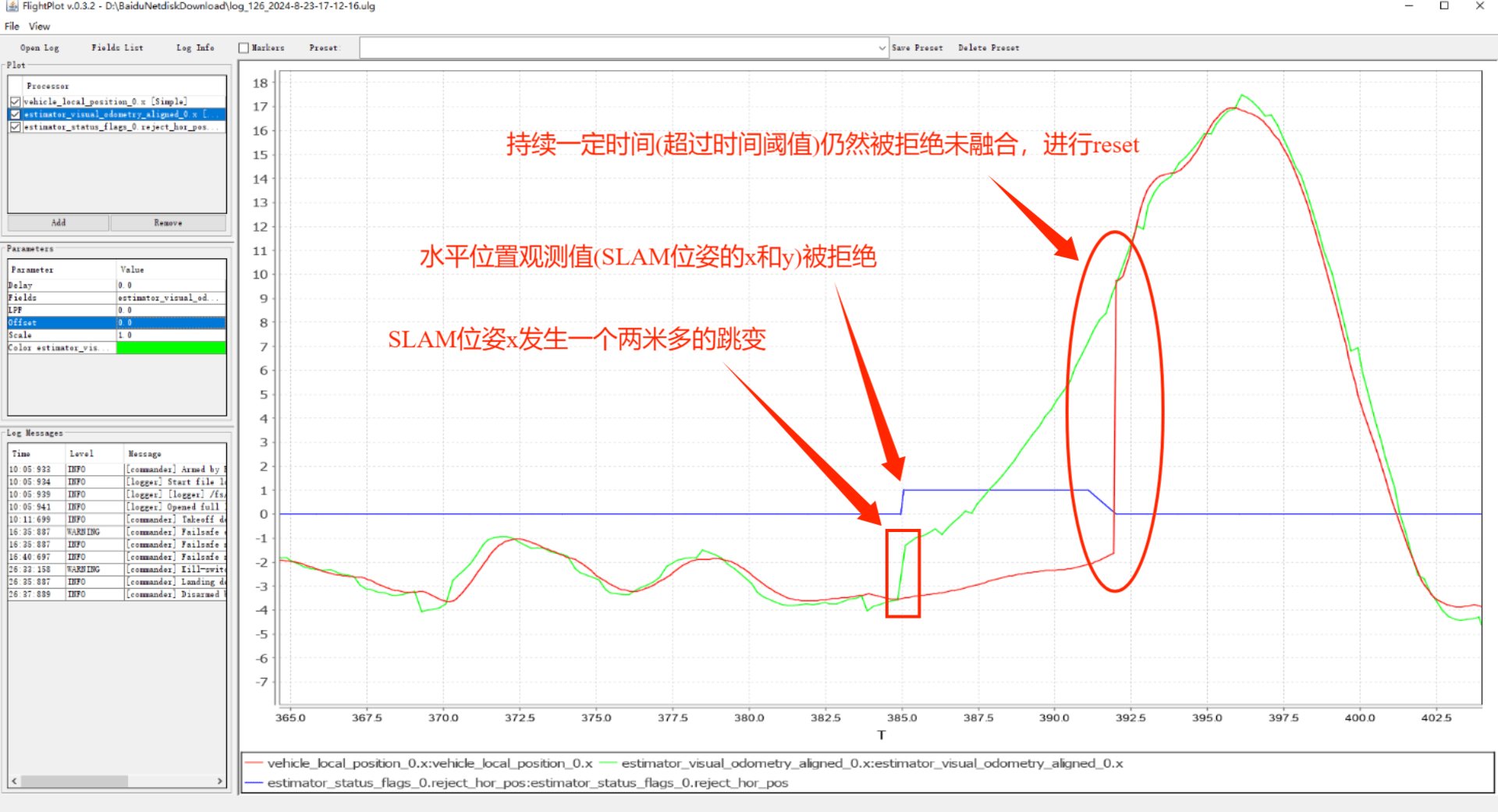
(注:此日志对应的px4飞控版本是1.12.3,出现innovation_rejected = true持续不融合进行reset的时间阈值是reset_timeout_max 7秒,本文讲解的是最新的PX4飞控代码,时间阈值是no_aid_timeout_max 1秒,这个注意下)
由此我们可以知道当SLAM位姿发生较大跳变,而reset_counter没有+1时,PX4端的EKF融合会发生什么情况。把Ekf::updateEvPosFusion函数看懂就可以对这个处理流程看得很清晰,Ekf::updateEvPosFusion函数本身也不长。
PX4-Autopilot\src\modules\ekf2\EKF\aid_sources\external_vision\ev_pos_control.cpp
void Ekf::updateEvPosFusion(const Vector2f &measurement, const Vector2f &measurement_var, bool quality_sufficient,
			    bool reset, estimator_aid_source2d_s &aid_src)
{
	if (reset) {

		if (quality_sufficient) {

			if (!_control_status.flags.gnss_pos) {
				ECL_INFO("reset to %s", EV_AID_SRC_NAME);
				_information_events.flags.reset_pos_to_vision = true;
				resetHorizontalPositionTo(measurement, measurement_var);
				_ev_pos_b_est.reset();

			} else {
				_ev_pos_b_est.setBias(-getLocalHorizontalPosition() + measurement);
			}

			aid_src.time_last_fuse = _time_delayed_us;

		} else {
			// EV has reset, but quality isn't sufficient
			// we have no choice but to stop EV and try to resume once quality is acceptable
			stopEvPosFusion();
			return;
		}

	} else if (quality_sufficient) {
		fuseHorizontalPosition(aid_src);

	} else {
		aid_src.innovation_rejected = true;
	}

	const bool is_fusion_failing = isTimedOut(aid_src.time_last_fuse, _params.no_aid_timeout_max); // 1 second

	if (is_fusion_failing) {
		bool pos_xy_fusion_failing = isTimedOut(_time_last_hor_pos_fuse, _params.no_aid_timeout_max);

		if ((_nb_ev_pos_reset_available > 0) && quality_sufficient) {
			// Data seems good, attempt a reset
			ECL_WARN("%s fusion failing, resetting", EV_AID_SRC_NAME);

			if (_control_status.flags.gnss_pos && !pos_xy_fusion_failing) {
				// reset EV position bias
				_ev_pos_b_est.setBias(-Vector2f(getLocalHorizontalPosition()) + measurement);

			} else {
				_information_events.flags.reset_pos_to_vision = true;

				if (_control_status.flags.gnss_pos) {
					resetHorizontalPositionTo(measurement - _ev_pos_b_est.getBias(), measurement_var + _ev_pos_b_est.getBiasVar());
					_ev_pos_b_est.setBias(-getLocalHorizontalPosition() + measurement);

				} else {
					resetHorizontalPositionTo(measurement, measurement_var);
					_ev_pos_b_est.reset();
				}
			}

			aid_src.time_last_fuse = _time_delayed_us;

			if (_control_status.flags.in_air) {
				_nb_ev_pos_reset_available--;
			}

		} else {
			// A reset did not fix the issue but all the starting checks are not passing
			// This could be a temporary issue, stop the fusion without declaring the sensor faulty
			ECL_WARN("stopping %s, fusion failing", EV_AID_SRC_NAME);
			stopEvPosFusion();
		}
	}
}
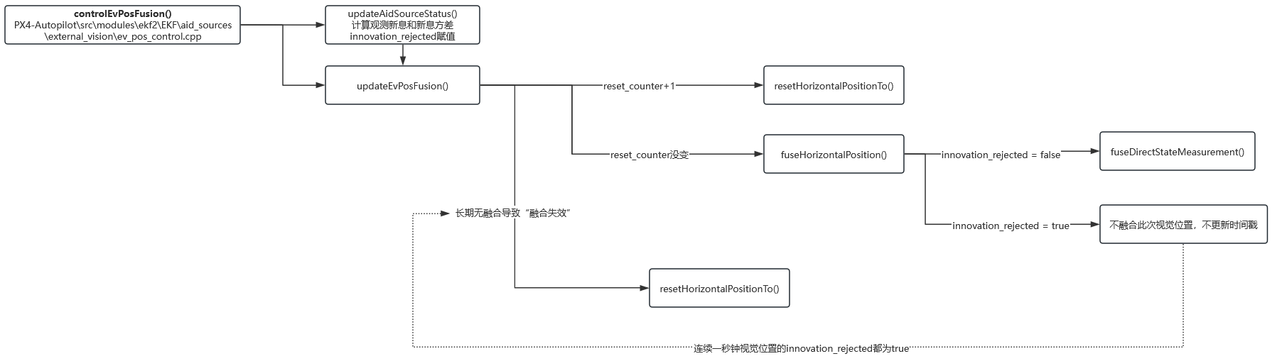
下图提炼出了Ekf::updateEvPosFusion函数的处理流程,通过这个图可以很好看出,当SLAM位姿出现大跳变时,有reset_counter + 1和没有reset_counter + 1的区别。有reset_counter + 1会直接立马很安全地重置,没有reset_counter + 1,会先拒绝融合导致无人机暂时先单纯靠imu估计位置,若持续1秒钟依旧拒绝融合视觉位置则会重置,若一秒钟内有视觉位置的新息通过了统计置信度检查,则继续正常融合,不会启动重置。
上面我们弄清楚了,当SLAM位姿发生较大跳变,而reset_counter 没有 + 1时,PX4端对位置融合的具体处理流程,现在我们再来详细看下当SLAM位姿发生较大跳变,而且reset_counter + 1时,PX4端又是如何处理的。
reset_counter + 1后会发生什么
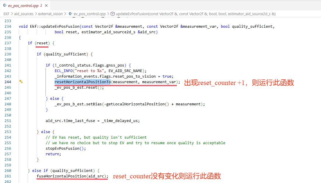
在updateEvPosFusion函数里可以看到,只要出现reset_counter+1,不管实际位姿有没有跳变,innovation_rejected是否为true,都会直接去运行resetHorizontalPositionTo函数,而不运行fuseHorizontalPosition函数了,resetHorizontalPositionTo函数如下。
PX4-Autopilot\src\modules\ekf2\EKF\position_fusion.cpp
void Ekf::resetHorizontalPositionTo(const double &new_latitude, const double &new_longitude,
				    const Vector2f &new_horz_pos_var)
{
	// 1. 计算跳变量:从当前 EKF 位置到新 SLAM 位置的 delta(用于 bias 补偿)
	const Vector2f delta_horz_pos = computeDeltaHorizontalPosition(new_latitude, new_longitude);

	// 2. 更新重置事件状态(供外部监控)
	updateHorizontalPositionResetStatus(delta_horz_pos);

#if defined(CONFIG_EKF2_EXTERNAL_VISION)
	// 3. 若当前使用 EV 位姿融合:调整 EV bias,使 bias 补偿量反映跳变
	//    即:bias_new = bias_old - delta_horz_pos
	//    这样后续观测仍可增量更新,避免 bias 发散
	if (_control_status.flags.ev_pos) {
		_ev_pos_b_est.setBias(_ev_pos_b_est.getBias() - delta_horz_pos);
	}
#endif // CONFIG_EKF2_EXTERNAL_VISION

	// 4. 更新全局位置(LLH)
	_gpos.setLatLonDeg(new_latitude, new_longitude);

	// 5. 更新输出预测器(用于控制律、日志等)
	_output_predictor.resetLatLonTo(new_latitude, new_longitude);

	// 6. 最关键:重置位置协方差(不确定性放大!)
	//    Pxx = max(0.01², new_horz_pos_var.x)   → 至少 1 cm²
	//    Pyy = max(0.01², new_horz_pos_var.y)
	if (PX4_ISFINITE(new_horz_pos_var(0))) {
		P.uncorrelateCovarianceSetVariance<1>(State::pos.idx, math::max(sq(0.01f), new_horz_pos_var(0)));
	}
	if (PX4_ISFINITE(new_horz_pos_var(1))) {
		P.uncorrelateCovarianceSetVariance<1>(State::pos.idx + 1, math::max(sq(0.01f), new_horz_pos_var(1)));
	}

	// 7. 重置超时计时器(防止误判 fusion failing)
	_time_last_hor_pos_fuse = _time_delayed_us;
}
resetHorizontalPositionTo是如何避免视觉位姿较大跳变后,EKF融合还保持稳定的呢,如果拒绝融合视觉位姿,这样无人机位置可能直接就飘了,如果强行融合,也可能不稳定。
其操作是通过“状态重置 + 协方差显式放大 + bias 对齐”,将大跳变转化为一个高不确定性的可信初始点,从而避免新息(innovation)因协方差过小而被拒融,保障后续融合稳定性。
重置后,EKF 的“输出”和“参考原点”立即跳变,而内部状态协方差被放大,内部滤波状态 _state.pos 仍保留原值,状态本身虽未强制覆盖,但因高不确定性,在后续融合中能快速跟随新观测。
上面详细讲了SLAM位姿发生较大跳变时,有reset_counter+1和没有reset_counter+1时,PX4 EKF2中对视觉位置融合的处理流程,当然我们用SLAM位姿定位时还会用到视觉位姿的偏航,我们也简单说下,SLAM位姿发生较大跳变时,视觉偏航融合时的处理流程,主要看PX4-Autopilot\src\modules\ekf2\EKF\aid_sources\external_vision\ev_yaw_control.cpp中的Ekf::controlEvYawFusion函数。
没有reset_counter+1时
创新过大导致 innov > gate * sqrt(innov_var),则 aid_src.innovation_rejected = true,但 fusion 不停,仅本次不融合——下次仍可融合。
如果长时间没有融合
自动执行 resetQuatStateYaw()函数,将 EKF 的四元数偏航部分强制对齐到当前 EV 的偏航观测值。
流程可整理成如下
SLAM 跳变 → innovation_rejected = true
        ↓
fuseYaw() 返回 false → 无融合,time_last_fuse 不更新
        ↓
1 秒后 → is_fusion_failing = true
        ↓
检查 _nb_ev_yaw_reset_available > 0?
        ├─ 是 → resetQuatStateYaw()(硬重置),如果是在空中飞行时 _nb_ev_yaw_reset_available减1
        └─ 否 → stopEvYawFusion()(停用 fusion,回退到其他 yaw 源)
说明一下:_nb_ev_yaw_reset_available 是一个空中重试计数器,用于限制在飞行中对 EV 偏航进行自动硬重置(resetQuatStateYaw)的次数,nb_ev_yaw_reset_available 仅在空中自动重置时减 1(因为超过1秒还没有融合成功时,不是主动reset_counter+1时),在每次成功恢复和视觉偏航的融合时_nb_ev_yaw_reset_available恢复为 5,在地面上自动重置时、主动reset_couner+1进行重置均不减 1,且永不自动增加。
有reset_counter+1时
执行
resetQuatStateYaw(obs, obs_var);
将 EKF 的四元数偏航部分强制对齐到当前 EV 的偏航观测值。
对于跳变的视觉位姿,除了EKF2这里要做好应对处理之外,控制模块也需要做好相应配合,避免因为位姿跳变带来的无人机飞行状态的突变或者不稳定。
下面讲讲reset_counter+1之后,PX4的控制器是如何进行协同的。
reset_counter与控制器协同
reset_counter的传递路径如下图所示
最终是通过vehicle_local_position uORB消息(VehicleLocalPosition.msg类型)和vehicle_attitude uORB消息(VehicleAttitude.msg类型)分别把对应的reset_counter传给位置控制器模块mc_pos_control和姿态控制器模块mc_att_control,使得位置控制器和姿态控制器做出相应的调整。

下面结合具体px4代码进行说明
https://docs.px4.io/main/zh/msg_docs/VehicleLocalPosition
https://github.com/PX4/PX4-Autopilot/blob/main/msg/versioned/VehicleLocalPosition.msg
vehicle_local_position uORB消息(VehicleLocalPosition.msg类型)里面含有xy_reset_counter z_reset_counter vxy_reset_counter vz_reset_counter heading_reset_counter
# Fused local position in NED.
# The coordinate system origin is the vehicle position at the time when the EKF2-module was started.

uint32 MESSAGE_VERSION = 1

uint64 timestamp			# time since system start (microseconds)
uint64 timestamp_sample                 # the timestamp of the raw data (microseconds)

bool xy_valid				# true if x and y are valid
bool z_valid				# true if z is valid
bool v_xy_valid				# true if vx and vy are valid
bool v_z_valid				# true if vz is valid

# Position in local NED frame
float32 x				# North position in NED earth-fixed frame, (metres)
float32 y				# East position in NED earth-fixed frame, (metres)
float32 z				# Down position (negative altitude) in NED earth-fixed frame, (metres)

# Position reset delta
float32[2] delta_xy			# Amount of lateral shift of position estimate in latest reset (in x and y) [m]
uint8 xy_reset_counter			# Index of latest lateral position estimate reset
float32 delta_z				# Amount of vertical shift of position estimate in latest reset [m]
uint8 z_reset_counter			# Index of latest vertical position estimate reset

# Velocity in NED frame
float32 vx 				# North velocity in NED earth-fixed frame, (metres/sec)
float32 vy				# East velocity in NED earth-fixed frame, (metres/sec)
float32 vz				# Down velocity in NED earth-fixed frame, (metres/sec)
float32 z_deriv				# Down position time derivative in NED earth-fixed frame, (metres/sec)

# Velocity reset delta
float32[2] delta_vxy			# Amount of lateral shift of velocity estimate in latest reset (in x and y) [m/s]
uint8 vxy_reset_counter			# Index of latest vertical velocity estimate reset
float32 delta_vz			# Amount of vertical shift of velocity estimate in latest reset [m/s]
uint8 vz_reset_counter			# Index of latest vertical velocity estimate reset

# Acceleration in NED frame
float32 ax        # North velocity derivative in NED earth-fixed frame, (metres/sec^2)
float32 ay        # East velocity derivative in NED earth-fixed frame, (metres/sec^2)
float32 az        # Down velocity derivative in NED earth-fixed frame, (metres/sec^2)

float32 heading				# Euler yaw angle transforming the tangent plane relative to NED earth-fixed frame, -PI..+PI,  (radians)
float32 heading_var
float32 unaided_heading                 # Same as heading but generated by integrating corrected gyro data only
float32 delta_heading			# Heading delta caused by latest heading reset [rad]
uint8 heading_reset_counter		# Index of latest heading reset
bool heading_good_for_control

float32 tilt_var

# Position of reference point (local NED frame origin) in global (GPS / WGS84) frame
bool xy_global				# true if position (x, y) has a valid global reference (ref_lat, ref_lon)
bool z_global				# true if z has a valid global reference (ref_alt)
uint64 ref_timestamp			# Time when reference position was set since system start, (microseconds)
float64 ref_lat				# Reference point latitude, (degrees)
float64 ref_lon				# Reference point longitude, (degrees)
float32 ref_alt				# Reference altitude AMSL, (metres)

# Distance to surface
bool dist_bottom_valid			# true if distance to bottom surface is valid
float32 dist_bottom			# Distance from from bottom surface to ground, (metres)
float32 dist_bottom_var                 # height above ground estimate variance (m^2)

float32 delta_dist_bottom               # Amount of vertical shift of dist bottom estimate in latest reset [m]
uint8 dist_bottom_reset_counter         # Index of latest dist bottom estimate reset

uint8 dist_bottom_sensor_bitfield	# bitfield indicating what type of sensor is used to estimate dist_bottom
uint8 DIST_BOTTOM_SENSOR_NONE = 0
uint8 DIST_BOTTOM_SENSOR_RANGE = 1	# (1 << 0) a range sensor is used to estimate dist_bottom field
uint8 DIST_BOTTOM_SENSOR_FLOW = 2	# (1 << 1) a flow sensor is used to estimate dist_bottom field (mostly fixed-wing use case)

float32 eph				# Standard deviation of horizontal position error, (metres)
float32 epv				# Standard deviation of vertical position error, (metres)
float32 evh				# Standard deviation of horizontal velocity error, (metres/sec)
float32 evv				# Standard deviation of vertical velocity error, (metres/sec)

bool dead_reckoning                     # True if this position is estimated through dead-reckoning

# estimator specified vehicle limits
# set to INFINITY when limiting not required
float32 vxy_max				# maximum horizontal speed (meters/sec)
float32 vz_max				# maximum vertical speed (meters/sec)
float32 hagl_min			# minimum height above ground level (meters)
float32 hagl_max_z			# maximum height above ground level for z-control (meters)
float32 hagl_max_xy			# maximum height above ground level for xy-control (meters)

# TOPICS vehicle_local_position vehicle_local_position_groundtruth external_ins_local_position
# TOPICS estimator_local_position
首先EKF2模块会发布的带有reset_counter的 estimator_local_position uORB 消息(VehicleLocalPosition.msg类型)
PX4-Autopilot\src\modules\ekf2\EKF2.cpp
_local_position_pub(multi_mode ? ORB_ID(estimator_local_position) : ORB_ID(vehicle_local_position)),
PX4-Autopilot\src\modules\ekf2\EKF2.cpp
void EKF2::PublishLocalPosition(const hrt_abstime ×tamp)
{
vehicle_local_position_s lpos{};
// generate vehicle local position data
lpos.timestamp_sample = timestamp;
// Position of body origin in local NED frame
const Vector3f position{_ekf.getPosition()};
lpos.x = position(0);
lpos.y = position(1);
lpos.z = position(2);
// Velocity of body origin in local NED frame (m/s)
const Vector3f velocity{_ekf.getVelocity()};
lpos.vx = velocity(0);
lpos.vy = velocity(1);
lpos.vz = velocity(2);
// vertical position time derivative (m/s)
lpos.z_deriv = _ekf.getVerticalPositionDerivative();
// Acceleration of body origin in local frame
const Vector3f vel_deriv{_ekf.getVelocityDerivative()};
_ekf.resetVelocityDerivativeAccumulation();
lpos.ax = vel_deriv(0);
lpos.ay = vel_deriv(1);
lpos.az = vel_deriv(2);
lpos.xy_valid = _ekf.isLocalHorizontalPositionValid();
lpos.v_xy_valid = _ekf.isLocalHorizontalPositionValid();
// TODO: some modules (e.g.: mc_pos_control) don't handle v_z_valid != z_valid properly
lpos.z_valid = _ekf.isLocalVerticalPositionValid() || _ekf.isLocalVerticalVelocityValid();
lpos.v_z_valid = _ekf.isLocalVerticalVelocityValid() || _ekf.isLocalVerticalPositionValid();
// Position of local NED origin in GPS / WGS84 frame
if (_ekf.global_origin_valid()) {
lpos.ref_timestamp = _ekf.global_origin().getProjectionReferenceTimestamp();
lpos.ref_lat = _ekf.global_origin().getProjectionReferenceLat(); // Reference point latitude in degrees
lpos.ref_lon = _ekf.global_origin().getProjectionReferenceLon(); // Reference point longitude in degrees
lpos.ref_alt = _ekf.getEkfGlobalOriginAltitude(); // Reference point in MSL altitude meters
lpos.xy_global = true;
lpos.z_global = true;
} else {
lpos.ref_timestamp = 0;
lpos.ref_lat = static_cast<double>(NAN);
lpos.ref_lon = static_cast<double>(NAN);
lpos.ref_alt = NAN;
lpos.xy_global = false;
lpos.z_global = false;
}
Quatf delta_q_reset;
_ekf.get_quat_reset(&delta_q_reset(0), &lpos.heading_reset_counter);
lpos.heading = Eulerf(_ekf.getQuaternion()).psi();
lpos.unaided_heading = _ekf.getUnaidedYaw();
lpos.heading_var = _ekf.getYawVar();
lpos.delta_heading = Eulerf(delta_q_reset).psi();
lpos.heading_good_for_control = _ekf.isYawFinalAlignComplete();
lpos.tilt_var = _ekf.getTiltVariance();
#if defined(CONFIG_EKF2_TERRAIN)
// Distance to bottom surface (ground) in meters, must be positive
lpos.dist_bottom_valid = _ekf.isTerrainEstimateValid() || (_ekf.getHeightSensorRef() == HeightSensor::RANGE);
lpos.dist_bottom = math::max(_ekf.getHagl(), 0.f);
lpos.dist_bottom_var = _ekf.getTerrainVariance();
_ekf.get_hagl_reset(&lpos.delta_dist_bottom, &lpos.dist_bottom_reset_counter);
lpos.dist_bottom_sensor_bitfield = vehicle_local_position_s::DIST_BOTTOM_SENSOR_NONE;
if (_ekf.control_status_flags().rng_terrain || _ekf.control_status_flags().rng_hgt) {
lpos.dist_bottom_sensor_bitfield |= vehicle_local_position_s::DIST_BOTTOM_SENSOR_RANGE;
}
if (_ekf.control_status_flags().opt_flow_terrain) {
lpos.dist_bottom_sensor_bitfield |= vehicle_local_position_s::DIST_BOTTOM_SENSOR_FLOW;
}
#endif // CONFIG_EKF2_TERRAIN
_ekf.get_ekf_lpos_accuracy(&lpos.eph, &lpos.epv);
_ekf.get_ekf_vel_accuracy(&lpos.evh, &lpos.evv);
// get state reset information of position and velocity
_ekf.get_posD_reset(&lpos.delta_z, &lpos.z_reset_counter);
_ekf.get_velD_reset(&lpos.delta_vz, &lpos.vz_reset_counter);
_ekf.get_posNE_reset(&lpos.delta_xy[0], &lpos.xy_reset_counter);
_ekf.get_velNE_reset(&lpos.delta_vxy[0], &lpos.vxy_reset_counter);
lpos.dead_reckoning = _ekf.control_status_flags().inertial_dead_reckoning
|| _ekf.control_status_flags().wind_dead_reckoning;
// get control limit information
_ekf.get_ekf_ctrl_limits(&lpos.vxy_max, &lpos.vz_max, &lpos.hagl_min, &lpos.hagl_max_z, &lpos.hagl_max_xy);
// convert NaN to INFINITY
if (!PX4_ISFINITE(lpos.vxy_max)) {
lpos.vxy_max = INFINITY;
}
if (!PX4_ISFINITE(lpos.vz_max)) {
lpos.vz_max = INFINITY;
}
if (!PX4_ISFINITE(lpos.hagl_min)) {
lpos.hagl_min = INFINITY;
}
if (!PX4_ISFINITE(lpos.hagl_max_z)) {
lpos.hagl_max_z = INFINITY;
}
if (!PX4_ISFINITE(lpos.hagl_max_xy)) {
lpos.hagl_max_xy = INFINITY;
}
// publish vehicle local position data
lpos.timestamp = _replay_mode ? timestamp : hrt_absolute_time();
_local_position_pub.publish(lpos);
}
在上面EKF2::PublishLocalPosition函数中对 estimator_local_position 的 xy_reset_counter 字段进行赋值的代码是:
_ekf.get_posNE_reset(&lpos.delta_xy[0], &lpos.xy_reset_counter);
解释:
lpos 是 vehicle_local_position_s 类型的结构体,但在此处(当 _local_position_pub 发布的是 estimator_local_position 时),它被用作 estimator_local_position 消息的载体。
get_posNE_reset(float delta_xy[2], uint8_t *xy_reset_counter) 是 EKF 对象(_ekf)的一个方法,用于获取东北方向(NED 的 NE 分量)位置重置的 增量 和 重置计数器。
该调用将 EKF 内部的 xy_reset_counter(即当前状态重置次数)写入到 lpos.xy_reset_counter,从而完成对 estimator_local_position.xy_reset_counter 字段的赋值。
EKF2Selector模块会订阅EKF2模块发布的带有reset_counter的 estimator_local_position uORB 消息(VehicleLocalPosition.msg类型),来生成并发布对应带有reset_counter的vehicle_local_position uORB消息(VehicleLocalPosition.msg类型)
PX4-Autopilot\src\modules\ekf2\EKF2Selector.cpp
void EKF2Selector::PublishVehicleLocalPosition()
{
	// 1. 从当前选中的 EKF 实例(_selected_instance)读取 estimator_local_position 消息
	vehicle_local_position_s local_position;

	// 若有新数据更新(uORB 订阅成功),则继续处理
	if (_instance[_selected_instance].estimator_local_position_sub.update(&local_position)) {
		bool instance_change = false;

		// 2. 检测是否切换了 EKF 实例(例如从 EKF2 切换到 EKF2_2)
		if (_instance[_selected_instance].estimator_local_position_sub.get_instance()
		    != _local_position_instance_prev) {
			_local_position_instance_prev = _instance[_selected_instance].estimator_local_position_sub.get_instance();
			instance_change = true;  // 标记:实例切换 → 需重新同步 reset 计数
		}

		// 3. 初始化:若这是第一次接收数据(_local_position_last.timestamp == 0),直接复制初始值
		if (_local_position_last.timestamp != 0) {
			// —— 下面是核心:根据 reset_counter 变化检测并累积重置事件 ——

			//  XY 位置重置(水平位置跳变)
			if (!instance_change && (local_position.xy_reset_counter == _local_position_last.xy_reset_counter + 1)) {
				// 情况(1):正常递增(EKF 主动 +1,说明是“可信重置”,使用 EKF 提供的 delta_xy)
				++_xy_reset_counter;  // 全局计数器累加(跨实例连续计数)
				_delta_xy_reset = Vector2f{local_position.delta_xy};  // 直接采用 EKF 计算的跳变量

			} else if (instance_change || (local_position.xy_reset_counter != _local_position_last.xy_reset_counter)) {
				// 情况(2):实例切换 或 非连续跳变(如 EKF 重启后从 0 开始计数)
				// → 无法信任 delta_xy(可能为 0 或无效),改用当前与上一帧的差值作为跳变量
				++_xy_reset_counter;
				_delta_xy_reset = Vector2f{local_position.x, local_position.y}
				                  - Vector2f{_local_position_last.x, _local_position_last.y};
			}

			//  Z 位置重置(高度跳变)—— 逻辑同上
			if (!instance_change && (local_position.z_reset_counter == _local_position_last.z_reset_counter + 1)) {
				++_z_reset_counter;
				_delta_z_reset = local_position.delta_z;
			} else if (instance_change || (local_position.z_reset_counter != _local_position_last.z_reset_counter)) {
				++_z_reset_counter;
				_delta_z_reset = local_position.z - _local_position_last.z;
			}

			//  VXY 速度重置(水平速度跳变)
			if (!instance_change && (local_position.vxy_reset_counter == _local_position_last.vxy_reset_counter + 1)) {
				++_vxy_reset_counter;
				_delta_vxy_reset = Vector2f{local_position.delta_vxy};
			} else if (instance_change || (local_position.vxy_reset_counter != _local_position_last.vxy_reset_counter)) {
				++_vxy_reset_counter;
				_delta_vxy_reset = Vector2f{local_position.vx, local_position.vy}
				                  - Vector2f{_local_position_last.vx, _local_position_last.vy};
			}

			//  VZ 速度重置(垂直速度跳变)
			if (!instance_change && (local_position.vz_reset_counter == _local_position_last.vz_reset_counter + 1)) {
				++_vz_reset_counter;
				_delta_vz_reset = local_position.delta_vz;
			} else if (instance_change || (local_position.vz_reset_counter != _local_position_last.vz_reset_counter)) {
				++_vz_reset_counter;
				_delta_vz_reset = local_position.vz - _local_position_last.vz;
			}

			//  heading 偏航重置
			if (!instance_change && (local_position.heading_reset_counter == _local_position_last.heading_reset_counter + 1)) {
				++_heading_reset_counter;
				_delta_heading_reset = local_position.delta_heading;
			} else if (instance_change || (local_position.heading_reset_counter != _local_position_last.heading_reset_counter)) {
				++_heading_reset_counter;
				_delta_heading_reset = matrix::wrap_pi(local_position.heading - _local_position_last.heading);
			}

			//  HAGL (height above ground level) 重置 —— 用于地形/激光测距
			if (!instance_change
			    && (local_position.dist_bottom_reset_counter == _local_position_last.dist_bottom_reset_counter + 1)) {
				++_hagl_reset_counter;
				_delta_hagl_reset = local_position.delta_dist_bottom;
			} else if (instance_change
				   || (local_position.dist_bottom_reset_counter != _local_position_last.dist_bottom_reset_counter)) {
				++_hagl_reset_counter;
				_delta_hagl_reset = local_position.dist_bottom - _local_position_last.dist_bottom;
			}

		} else {
			//  首次接收数据:直接初始化全局 reset counter 和 delta 值
			_xy_reset_counter = local_position.xy_reset_counter;
			_z_reset_counter = local_position.z_reset_counter;
			_vxy_reset_counter = local_position.vxy_reset_counter;
			_vz_reset_counter = local_position.vz_reset_counter;
			_heading_reset_counter = local_position.heading_reset_counter;
			_hagl_reset_counter = local_position.dist_bottom_reset_counter;

			_delta_xy_reset = Vector2f{local_position.delta_xy};
			_delta_z_reset = local_position.delta_z;
			_delta_vxy_reset = Vector2f{local_position.delta_vxy};
			_delta_vz_reset = local_position.delta_vz;
			_delta_heading_reset = local_position.delta_heading;
			_delta_hagl_reset = local_position.delta_dist_bottom;
		}

		// 4. 决定是否发布:防重复/过期数据
		bool publish = true;

		//  安全检查:避免时间倒流或消息过期(>20ms 视为无效)
		//   - timestamp_sample 用于控制律时间戳连续性
		//   - timestamp 用于消息时效性(防延迟消息误用)
		if ((local_position.timestamp_sample <= _local_position_last.timestamp_sample)
		    || (hrt_elapsed_time(&local_position.timestamp) > 20_ms)) {
			publish = false;
		}

		// 5. 保存当前帧为“上一帧”,用于下一次比较
		_local_position_last = local_position;

		// 6. 若通过检查,发布最终的 vehicle_local_position 消息
		if (publish) {
			//  填充:将**累积的全局 reset counter** 和 **累计 delta** 写入消息
			local_position.xy_reset_counter = _xy_reset_counter;
			local_position.z_reset_counter = _z_reset_counter;
			local_position.vxy_reset_counter = _vxy_reset_counter;
			local_position.vz_reset_counter = _vz_reset_counter;
			local_position.heading_reset_counter = _heading_reset_counter;
			local_position.dist_bottom_reset_counter = _hagl_reset_counter;

			//  填充:将**累计跳变量**(_delta_*_reset)写入 delta 字段
			_delta_xy_reset.copyTo(local_position.delta_xy);
			local_position.delta_z = _delta_z_reset;
			_delta_vxy_reset.copyTo(local_position.delta_vxy);
			local_position.delta_vz = _delta_vz_reset;
			local_position.delta_heading = _delta_heading_reset;
			// 注意:dist_bottom 的 delta 已在前面赋值(未显式覆盖,因 local_position.delta_dist_bottom 为 float)

			//  更新时间戳为当前系统时间
			local_position.timestamp = hrt_absolute_time();

			//  发布到 uORB,供 mc_pos_control、navigator 等模块订阅
			_vehicle_local_position_pub.publish(local_position);
		}
	}
}
estimator_attitude uORB消息和vehicle_attitude uORB消息都是VehicleAttitude.msg类型
https://docs.px4.io/main/zh/msg_docs/VehicleAttitude
https://github.com/PX4/PX4-Autopilot/blob/main/msg/versioned/VehicleAttitude.msg
# This is similar to the mavlink message ATTITUDE_QUATERNION, but for onboard use
# The quaternion uses the Hamilton convention, and the order is q(w, x, y, z)

uint32 MESSAGE_VERSION = 0

uint64 timestamp                # time since system start (microseconds)

uint64 timestamp_sample         # the timestamp of the raw data (microseconds)

float32[4] q                    # Quaternion rotation from the FRD body frame to the NED earth frame
float32[4] delta_q_reset        # Amount by which quaternion has changed during last reset
uint8 quat_reset_counter        # Quaternion reset counter

# TOPICS vehicle_attitude vehicle_attitude_groundtruth external_ins_attitude
# TOPICS estimator_attitude
EKF2 模块先发布 estimator_attitude,其中包含其自身触发的单次重置信息;EKF2Selector 负责将其“标准化”为统一的 vehicle_attitude。 这是PX4 的分层架构设计,EKF2是单纯地做估计,支持多实例并行运行,EKF2Selector从多个 estimator_attitude 实例中选择最优实例,累积 reset 计数(跨实例连续),生成统一、可靠的标准姿态消息,供所有控制器(如 mc_att_control)使用,所以叫EKF2Selector。
PX4-Autopilot\src\modules\ekf2\EKF2.cpp
void EKF2::PublishAttitude(const hrt_abstime ×tamp)
{
if (_ekf.attitude_valid()) {
// generate vehicle attitude quaternion data
vehicle_attitude_s att;
att.timestamp_sample = timestamp;
_ekf.getQuaternion().copyTo(att.q);
_ekf.get_quat_reset(&att.delta_q_reset[0], &att.quat_reset_counter);
att.timestamp = _replay_mode ? timestamp : hrt_absolute_time();
_attitude_pub.publish(att);
} else if (_replay_mode) {
// in replay mode we have to tell the replay module not to wait for an update
// we do this by publishing an attitude with zero timestamp
vehicle_attitude_s att{};
_attitude_pub.publish(att);
}
}
EKF2Selector模块订阅EKF2模块发布的estimator_attitude uORB消息,然后发布vehicle_attitude uORB消息。
PX4-Autopilot\src\modules\ekf2\EKF2Selector.cpp
void EKF2Selector::PublishVehicleAttitude()
{
	// selected estimator_attitude -> vehicle_attitude
	vehicle_attitude_s attitude;

	if (_instance[_selected_instance].estimator_attitude_sub.update(&attitude)) {
		bool instance_change = false;

		if (_instance[_selected_instance].estimator_attitude_sub.get_instance() != _attitude_instance_prev) {
			_attitude_instance_prev = _instance[_selected_instance].estimator_attitude_sub.get_instance();
			instance_change = true;
		}

		if (_attitude_last.timestamp != 0) {
			if (!instance_change && (attitude.quat_reset_counter == _attitude_last.quat_reset_counter + 1)) {
				// propogate deltas from estimator data while maintaining the overall reset counts
				++_quat_reset_counter;
				_delta_q_reset = Quatf{attitude.delta_q_reset};

			} else if (instance_change || (attitude.quat_reset_counter != _attitude_last.quat_reset_counter)) {
				// on reset compute deltas from last published data
				++_quat_reset_counter;
				_delta_q_reset = (Quatf(attitude.q) * Quatf(_attitude_last.q).inversed()).normalized();
			}

		} else {
			_quat_reset_counter = attitude.quat_reset_counter;
			_delta_q_reset = Quatf{attitude.delta_q_reset};
		}

		bool publish = true;

		// ensure monotonically increasing timestamp_sample through reset, don't publish
		//  estimator's attitude for system (vehicle_attitude) if it's stale
		if ((attitude.timestamp_sample <= _attitude_last.timestamp_sample)
		    || (hrt_elapsed_time(&attitude.timestamp) > 10_ms)) {

			publish = false;
		}

		// save last primary estimator_attitude as published with original resets
		_attitude_last = attitude;

		if (publish) {
			// republish with total reset count and current timestamp
			attitude.quat_reset_counter = _quat_reset_counter;
			_delta_q_reset.copyTo(attitude.delta_q_reset);

			attitude.timestamp = hrt_absolute_time();
			_vehicle_attitude_pub.publish(attitude);
		}
	}
}
mc_pos_control模块会订阅EKF2模块发布的带有reset_counter的vehicle_local_position uORB消息(VehicleLocalPosition.msg类型),判断其中对应的reset_counter有没有发生变化,做出一些对应调整措施。
PX4-Autopilot\src\modules\mc_pos_control\MulticopterPositionControl.cpp
void MulticopterPositionControl::adjustSetpointForEKFResets(const vehicle_local_position_s &vehicle_local_position,
		trajectory_setpoint_s &setpoint)
{
	// 1. 仅当 setpoint 时间早于 vehicle_local_position(即 setpoint 尚未用新位姿更新),才需补偿
	if ((setpoint.timestamp != 0) && (setpoint.timestamp < vehicle_local_position.timestamp)) {

		// 2. 检测各维度的 reset_counter 是否变化 → 若变化,说明 EKF 刚重置了该状态
		if (vehicle_local_position.vxy_reset_counter != _vxy_reset_counter) {
			// EKF 重置了水平速度 → 将 delta_vxy(EKF 记录的跳变量)加到 setpoint 速度上
			setpoint.velocity[0] += vehicle_local_position.delta_vxy[0];
			setpoint.velocity[1] += vehicle_local_position.delta_vxy[1];
		}

		if (vehicle_local_position.vz_reset_counter != _vz_reset_counter) {
			setpoint.velocity[2] += vehicle_local_position.delta_vz;  // 垂直速度补偿
		}

		if (vehicle_local_position.xy_reset_counter != _xy_reset_counter) {
			// EKF 重置了水平位置 → 补偿 setpoint 位置
			setpoint.position[0] += vehicle_local_position.delta_xy[0];
			setpoint.position[1] += vehicle_local_position.delta_xy[1];
		}

		if (vehicle_local_position.z_reset_counter != _z_reset_counter) {
			setpoint.position[2] += vehicle_local_position.delta_z;  // 高度补偿
		}

		if (vehicle_local_position.heading_reset_counter != _heading_reset_counter) {
			setpoint.yaw = wrap_pi(setpoint.yaw + vehicle_local_position.delta_heading);  // 偏航补偿
		}
	}

	// 3. 同步滤波器状态:重置 LPF/Notch 滤波器,避免因跳变产生瞬时大输出
	if (vehicle_local_position.vxy_reset_counter != _vxy_reset_counter) {
		_vel_xy_lp_filter.reset(_vel_xy_lp_filter.getState() + Vector2f(vehicle_local_position.delta_vxy));
		_vel_xy_notch_filter.reset();  // 消除因跳变引起的滤波器延迟/振荡
	}

	if (vehicle_local_position.vz_reset_counter != _vz_reset_counter) {
		_vel_z_lp_filter.reset(_vel_z_lp_filter.getState() + vehicle_local_position.delta_vz);
		_vel_z_notch_filter.reset();
	}

	// 4. 保存最新 reset_counter,用于下次比较(防止重复补偿)
	_vxy_reset_counter = vehicle_local_position.vxy_reset_counter;
	_vz_reset_counter = vehicle_local_position.vz_reset_counter;
	_xy_reset_counter = vehicle_local_position.xy_reset_counter;
	_z_reset_counter = vehicle_local_position.z_reset_counter;
	_heading_reset_counter = vehicle_local_position.heading_reset_counter;
}
核心调整措施是两个步骤
(1)补偿轨迹设定点(setpoint)
若 vehicle_local_position.xy_reset_counter != _xy_reset_counter:
将 delta_xy 加到当前 setpoint.position 上:
setpoint.position[0] += vehicle_local_position.delta_xy[0];
setpoint.position[1] += vehicle_local_position.delta_xy[1];
同理补偿 z, vx/vy, vz, yaw。
这确保了:即使 EKF 突然把当前位置(local position)移动了 Δ,控制器仍认为无人机“没动” —— 因为它把期望位置点也同步移动了 Δ。
(2)重置低通/陷波滤波器
_vel_xy_lp_filter.reset(_vel_xy_lp_filter.getState() + Vector2f(delta_vxy));
_vel_xy_notch_filter.reset();
防止因速度跳变导致滤波器输出瞬时突变(如积分项饱和、震荡)→ 防止剧烈抖动或姿态突变;
避免因历史状态残留引发控制输出毛刺(如电机突加推力)。
这是姿态控制器模块订阅到EKF2Selector模块发布vehicle_attitude uORB消息后,如果消息里的quat_reset_counter + 1了,则执行相应操作应对偏航的突变。
PX4-Autopilot\src\modules\mc_att_control\mc_att_control_main.cpp
	// run controller on attitude updates
	vehicle_attitude_s v_att;

	if (_vehicle_attitude_sub.update(&v_att)) {


			// Check for a heading reset
			if (_quat_reset_counter != v_att.quat_reset_counter) {
				const Quatf delta_q_reset(v_att.delta_q_reset);
				const float delta_psi = Eulerf(delta_q_reset).psi();

				// Only offset the yaw setpoint when the heading is locked
				if (PX4_ISFINITE(_yaw_setpoint_stabilized)) {
					_yaw_setpoint_stabilized = wrap_pi(_yaw_setpoint_stabilized + delta_psi);
				}

				_stick_yaw.ekfResetHandler(delta_psi);

				if (v_att.timestamp > _last_attitude_setpoint) {
					// adapt existing attitude setpoint unless it was generated after the current attitude estimate
					_attitude_control.adaptAttitudeSetpoint(delta_q_reset);
				}

				_quat_reset_counter = v_att.quat_reset_counter;
			}
这里面最关键的一步是更新期望姿态(attitude setpoint),这样可以保证偏航突变的时候姿态环输出稳定,从而保证无人机姿态稳定。
_attitude_control.adaptAttitudeSetpoint(delta_q_reset);
除了飞控内部控制环对reset_counter+1的主动处理外,我们还可以通过设置MPC_XY_VEL_ALL飞控参数来限制无人机最大水平速度,设置MPC_TILTMAX_AIR飞控参数来限制无人机最大倾角的方式来防止因为视觉位姿跳变可能引起的无人机位姿的突变的不稳情况,加上双重保障。
quality
int8 类型,表示质量指标,但当前在 PX4 中未使用(注释中明确标注 Unused),且当值为 0 时被视为无效([@invalid 0])。 所以直接赋值为0就行。
实际在PX4的EKF2代码里,quality 只是作为一个门限判断,比如quality大于某个值,就代表视觉位姿数据OK,可以进行融合,小于某个值,则不融合视觉位姿,这个阈值由飞控参数 ekf2_ev_qmin 配置,默认是0。quality 本身不参与数据融合过程,EKF2 不根据 quality 动态调整观测噪声(如 position_var, velocity_var, orientation_var)。
PX4的EKF2中quality相关代码如下
PX4-Autopilot\src\modules\ekf2\params_external_vision.yaml
    EKF2_EV_QMIN:
      description:
        short: External vision (EV) minimum quality (optional)
        long: External vision will only be started and fused if the quality metric
          is above this threshold. The quality metric is a completely optional field
          provided by some VIO systems.
      type: int32
      default: 0
      min: 0
      max: 100
      decimal: 1
PX4-Autopilot\src\modules\ekf2\EKF\common.h
int32_t ekf2_ev_qmin{0}; ///< vision minimum acceptable quality integer
PX4-Autopilot\src\modules\ekf2\EKF\aid_sources\external_vision\ev_control.cpp
		bool ev_reset = (ev_sample.reset_counter != _ev_sample_prev.reset_counter);

		// determine if we should use the horizontal position observations
		bool quality_sufficient = (_params.ekf2_ev_qmin <= 0) || (ev_sample.quality >= _params.ekf2_ev_qmin);

		const bool starting_conditions_passing = quality_sufficient
				&& ((ev_sample.time_us - _ev_sample_prev.time_us) < EV_MAX_INTERVAL)
				&& ((_params.ekf2_ev_qmin <= 0)
				    || (_ev_sample_prev.quality >= _params.ekf2_ev_qmin)) // previous quality sufficient
				&& ((_params.ekf2_ev_qmin <= 0)
				    || (_ext_vision_buffer->get_newest().quality >= _params.ekf2_ev_qmin)) // newest quality sufficient
				&& isNewestSampleRecent(_time_last_ext_vision_buffer_push, EV_MAX_INTERVAL);

		updateEvAttitudeErrorFilter(ev_sample, ev_reset);

		controlEvYawFusion(imu_sample, ev_sample, starting_conditions_passing, ev_reset, quality_sufficient, _aid_src_ev_yaw);
最主要的判断逻辑是这一句
PX4-Autopilot\src\modules\ekf2\EKF\aid_sources\external_vision\ev_control.cpp
bool quality_sufficient = (_params.ekf2_ev_qmin <= 0) || (ev_sample.quality >= _params.ekf2_ev_qmin);
_params.ekf2_ev_qmin 来自参数 EKF2_EV_QMIN(默认为 0);
若 ekf2_ev_qmin > 0,则只有 ev_sample.quality >= ekf2_ev_qmin 时,quality_sufficient = true,表示启用质量阈值检查;
若 ekf2_ev_qmin <= 0,因为ekf2_ev_qmin可配置的最小值就是0,所以实际意思是若ekf2_ev_qmin == 0,此时quality_sufficient衡为true,没有对ev_sample.quality做检查,表示不启用质量阈值检查,所以默认情况下也就是ekf2_ev_qmin的值为0的情况下,quality是不起作用的。
后面const bool starting_conditions_passing的代码里quality的判断逻辑本质也是这样
所以quality我们直接赋值为0就可以,不影响,默认情况下不检查它,unused。
而且多说一下,reset判断和quality判断是视觉位姿融合函数里面最开始的两个判断,而且相关融合参数的传参里面都有这两个参数,像下面函数里面的ev_reset和quality_sufficient。
		controlEvYawFusion(imu_sample, ev_sample, starting_conditions_passing, ev_reset, quality_sufficient, _aid_src_ev_yaw);
		controlEvVelFusion(ev_vel_ned, starting_conditions_passing, ev_reset, quality_sufficient, _aid_src_ev_vel);
		controlEvPosFusion(imu_sample, ev_sample, starting_conditions_passing, ev_reset, quality_sufficient, _aid_src_ev_pos);
		controlEvHeightFusion(imu_sample, ev_sample, starting_conditions_passing, ev_reset, quality_sufficient,
				      _aid_src_ev_hgt);
坐标系变换
我们通过mavros给PX4发送位姿时,mavros完成了其中的坐标系变换,现在不用mavros通过micro XRCE-DDS后,需要我们自己来完成这些坐标系变换。
在用mavros时,mavros作为连接飞控端和ros端的程序,有这么四个坐标系,即飞控端的body系和local系及ros端的body系和local系:fcu_body,fcu_local,ros_body,ros_local。 其中fcu_body又叫aircraft坐标系,是FRD坐标系,是px4所使用的body系,ros_body又叫baselink坐标系,是FLU坐标系,是mavros所使用的body系(在ROS-kinetic版本的mavros中,ros_body系是RFU坐标系,X轴指向右,Y轴指向前。而在ROS-melodic及之后的版本中,ros_body系是FLU坐标系。
我们在ROS层面看到的比如/mavros/local_position/pose或者/mavros/vision_pose/pose里面的位姿对应的是ros_body坐标系在ros_local坐标系下的位姿。 我们在QGC看到的飞控的一些mavlink消息如local_position和attitude里的位姿对应的是fcu_body在fcu_local下的位姿。
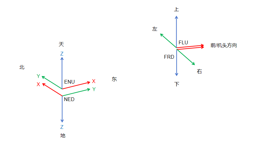
https://docs.px4.io/main/zh/ros2/user_guide#ros-2-px4-%E5%9D%90%E6%A0%87%E7%B3%BB%E5%85%AC%E7%BA%A6
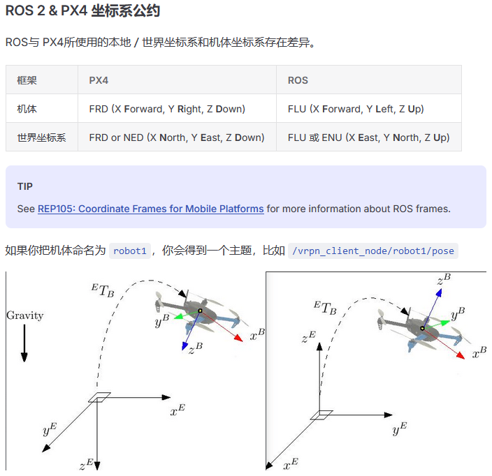
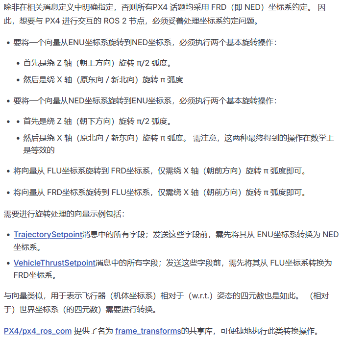
虽然PX4/px4_ros_com 提供了名为 frame_transforms的共享库,可便捷地执行此类转换操作,但是个人觉得完全可以自己弄。
坐标系变换也不难,关键点就是两个,找到当前body系到FRD body系的旋转矩阵,找到当前世界系到NED世界系的旋转矩阵,代码上借助eigen可以轻松完整相应旋转操作。
我们首先确定好几个坐标系,以及几个坐标系之间的变换矩阵
SLAM位姿中的世界系我这里写为w,也叫重力对齐后的世界系,因为带imu的SLAM一般会对世界系做重力对齐,其世界系一般都是重力对齐后的世界系。SLAM位姿中的body系写为b,一般是imu坐标系或者相机系,变换后的世界系也就是北东地世界系写为ned,变换后的body系也就是前右下坐标系写为frd。
Tfrdned=Twned⋅Tbw⋅TfrdbT^{\text{ned}}_{\text{frd}} = T^{\text{ned}}_{\text{w}} \cdot T^{\text{w}}_{\text{b}} \cdot T^{\text{b}}_{\text{frd}}Tfrdned=Twned⋅Tbw⋅Tfrdb
//w 重力对齐后的世界系  ned 北东地坐标系  frd 前右下坐标系  b body坐标系(相机系或imu坐标系)
Eigen::Isometry3d T_frd_ned ,T_b_w ,T_w_ned ,T_frd_b  ;  //变换矩阵
我们所做的坐标系变换其实就是以下操作,把ROS2端的SLAM位姿T_w_b(body系在相应重力对齐世界系下的位姿)推导得到FRD坐标系在NED坐标系下的位姿T_ned_frd,只需要确定好T_ned_w和T_b_frd这两个变换矩阵即可,而且只用确定T_ned_w和T_b_frd中的旋转矩阵部分,平移向量都是(0,0,0),因为body坐标系和FRD坐标系的原点是重合的,SLAM中重力对齐后的世界系和NED坐标系的原点也是重合的。。
T_frd_ned = T_w_ned * T_b_w * T_frd_b
下面以基于D435i imu的vinsfusion为例
ros2版本的vinsfusiongpu可见:https://github.com/zinuok/VINS-Fusion-ROS2
vinsfusion发出的/vins_fusion/odometry位姿话题是以imu为body系,世界系是imu坐标系做了重力对齐后的坐标系,即y轴朝前,x轴朝右边,z轴朝上。
当D435i平放时,vinsfusion输出/vins_fusion/odometry位姿话题的位姿的body系和世界系如下图所示
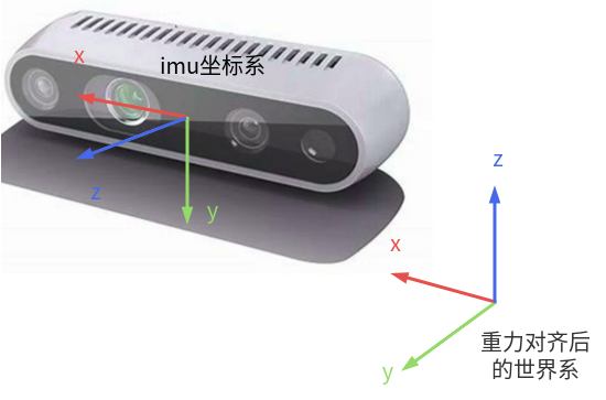
我们需要做的坐标系变换如下图所示
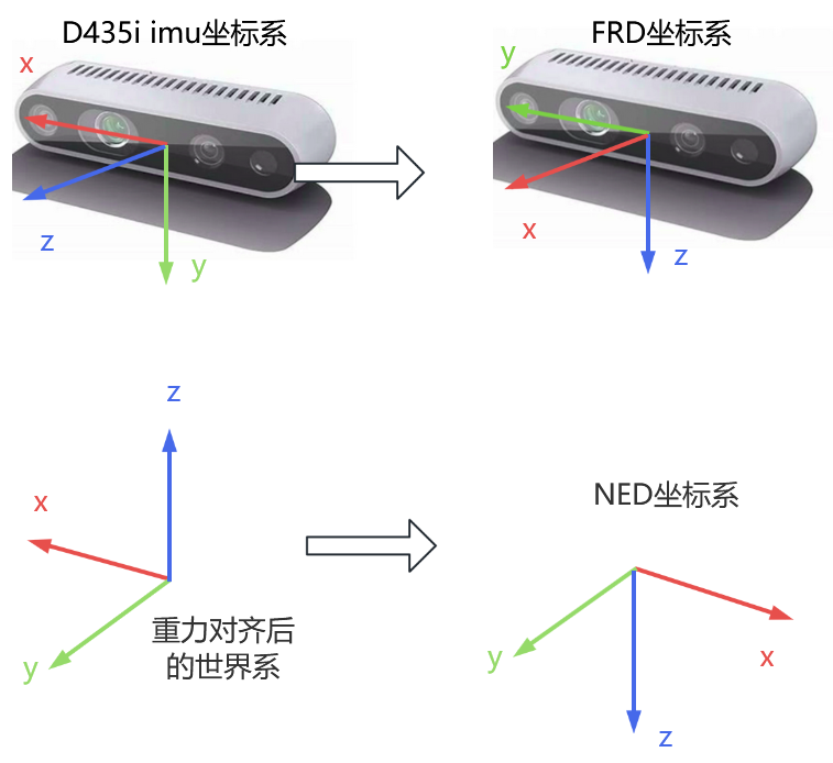
由图可知,关键是确定两个旋转矩阵RwnedR_{w}^{\text{ned}}Rwned和Rfrd bR_{\text{frd}}^{\,b}Rfrdb,代码中是rotation_matrix_w_ned 和rotation_matrix_frd_b ,旋转矩阵的确定有小技巧,如果是这种90度倍速的旋转,对应的旋转矩阵可以肉眼推算出来,对比两个坐标系xyz轴的对应关系。
比如w坐标系的x轴朝向和ned坐标系的x轴朝向相反,那就在旋转矩阵,纵向为x_w,横向为x_ned的位置写-1,再比如frd坐标系的x轴朝向和b坐标系的z轴朝向一致,那就在旋转矩阵,纵向为x_frd,横向为z_b的位置写1,其他的以此类推便可以很轻松得到旋转矩阵RwnedR_{w}^{\text{ned}}Rwned和Rfrd bR_{\text{frd}}^{\,b}Rfrdb,即代码中的rotation_matrix_w_ned 和rotation_matrix_frd_b。
(xnedynedzned)=(−10001000−1)xwywzw\begin{pmatrix} x_{\text{ned}} \\ y_{\text{ned}} \\ z_{\text{ned}} \end{pmatrix} = \overset{ \begin{array}{ccc} x_w & y_w & z_w \end{array} }{ \begin{pmatrix} -1 & 0 & 0 \\ 0 & 1 & 0 \\ 0 & 0 & -1 \end{pmatrix} } xnedynedzned = −10001000−1 xwywzw
(xbybzb)=(010001100)xfrdyfrdzfrd\begin{pmatrix} x_{\text{b}} \\ y_{\text{b}} \\ z_{\text{b}} \end{pmatrix} = \overset{ \begin{array}{ccc} x_{\text{frd}} & y_{\text{frd}} & z_{\text{frd}} \end{array} }{ \begin{pmatrix} 0 & 1 & 0 \\ 0 & 0 & 1 \\ 1 & 0 & 0 \end{pmatrix} } xbybzb = 001100010 xfrdyfrdzfrd
Eigen::Matrix3d rotation_matrix_w_ned ,rotation_matrix_frd_b ;

Eigen::Vector3d t_w_ned ,t_frd_b ;

    t_w_ned <<  0, 0, 0;
    rotation_matrix_w_ned << -1, 0, 0,
                          0 , 1, 0,
                          0, 0, -1;
    T_w_ned.linear() = rotation_matrix_w_ned ;
    T_w_ned.translation() = t_w_ned;

    t_frd_b <<  0, 0, 0;
    rotation_matrix_frd_b << 0, 1, 0,
                          0 , 0, 1,
                          1, 0, 0;
    T_frd_b.linear() = rotation_matrix_frd_b ;
    T_frd_b.translation() = t_frd_b;
ROS2转换节点编写
PX4 官方有提供一些 ROS 2 示例程序可以供参考 px4_ros_com(https://github.com/PX4/px4_ros_com)
以 px4_ros_com/src/advertisers 路径下的 debug_vect_advertiser.cpp ( https://github.com/PX4/px4_ros_com/blob/main/src/examples/advertisers/debug_vect_advertiser.cpp )为例。主要演示如何创建一个基本的发布px4_msgs::msg::DebugVect.msg类型话题的ROS2节点。
首先我们会导入所需的headers,其中包括DebugVect.msg消息头文件px4_msgs/msg/debug_vect.hpp。
#include <chrono>
#include <rclcpp/rclcpp.hpp>
#include <px4_msgs/msg/debug_vect.hpp>

using namespace std::chrono_literals;
随后,代码创建了一个 DebugVectAdvertiser 类,该类继承自通用的 rclcpp::Node 基类。
class DebugVectAdvertiser : public rclcpp::Node
{
这段代码创建了一个用来发送消息的回调函数。 发送消息的回调函数由定时器触发的,每秒钟发送两次消息。
public:
  DebugVectAdvertiser() : Node("debug_vect_advertiser") {
    publisher_ = this->create_publisher<px4_msgs::msg::DebugVect>("/fmu/in/debug_vect", 10);
    auto timer_callback =
    [this]()->void {
      auto debug_vect = px4_msgs::msg::DebugVect();
      debug_vect.timestamp = std::chrono::time_point_cast<std::chrono::microseconds>(std::chrono::steady_clock::now()).time_since_epoch().count();
      std::string name = "test";
      std::copy(name.begin(), name.end(), debug_vect.name.begin());
      debug_vect.x = 1.0;
      debug_vect.y = 2.0;
      debug_vect.z = 3.0;
      RCLCPP_INFO(this->get_logger(), "\033[97m Publishing debug_vect: time: %llu x: %f y: %f z: %f \033[0m",
                                    debug_vect.timestamp, debug_vect.x, debug_vect.y, debug_vect.z);
      this->publisher_->publish(debug_vect);
    };
    timer_ = this->create_wall_timer(500ms, timer_callback);
  }

private:
  rclcpp::TimerBase::SharedPtr timer_;
  rclcpp::Publisher<px4_msgs::msg::DebugVect>::SharedPtr publisher_;
};
这段代码在 main 函数中将 DebugVectAdvertiser 类实例化成一个ROS节点。
int main(int argc, char *argv[])
{
  std::cout << "Starting debug_vect advertiser node..." << std::endl;
  setvbuf(stdout, NULL, _IONBF, BUFSIZ);
  rclcpp::init(argc, argv);
  rclcpp::spin(std::make_shared<DebugVectAdvertiser>());

  rclcpp::shutdown();
  return 0;
}
px4文档里也有给一个把SLAM位姿转为/fmu/in/vehicle_visual_odometry的示例代码,可以参考。
https://docs.px4.io/main/zh/ros2/px4_ros2_navigation_interface
PX4 ROS 2 Interface Library 中的导航接口,支持开发者直接从 ROS 2 应用(如视觉惯性里程计系统或地图匹配系统)向 PX4 发送位置测量数据。 该接口提供了对 PX4 和 uORB 消息框架的抽象层,并对通过该接口发送的请求状态估计更新引入了一些合理性检查。 这些测量数据随后会被融合到扩展EKF中,其处理方式与 PX4 内部生成的测量数据完全一致。
此接口库提供两个类,LocalPositionMeasurementInterface 和 GlobalPositionMeasureInterface 它都会暴露出一个类似的 “update” 方法来提供一个本地位置或全球位置更新到 PX4。 update方法需要一个位置测量struct(LocalPositionMeasure](https://auterion.github.io/px4-ros2-interface-lib/structpx4__ros2_1_1LocalPositionMeasurement.html)或GlobalPositionMeasure],开发者可以在其中填入自己生成的位置测量数据。
https://github.com/Auterion/px4-ros2-interface-lib/blob/main/px4_ros2_cpp/include/px4_ros2/navigation/experimental/local_position_measurement_interface.hpp
https://github.com/Auterion/px4-ros2-interface-lib/blob/main/px4_ros2_cpp/src/navigation/experimental/local_position_measurement_interface.cpp
这个我没有使用过,可以参考,而且这个没有考虑到reset_counter,没有坐标系变换。
我觉得把SLAM位姿转为/fmu/in/vehicle_visual_odometry这个功能自己来写也是没有问题的,不复杂。
下面说下如何自己来写这么一个把SLAM位姿转为合格的/fmu/in/vehicle_visual_odometry话题的ROS2节点。
QoS
https://fishros.org.cn/forum/topic/1757/ros2%E9%80%9A%E8%AE%AF%E6%9C%8D%E5%8A%A1%E8%B4%A8%E9%87%8Fqos%E4%BB%8B%E7%BB%8D%E4%B8%8E%E6%A0%B7%E4%BE%8B
QoS policies (策略):
当前的基本QoS配置文件包括以下策略设置:
History (历史):
- Keep last (仅保留最新): 仅存储最多N个样本,N 由 Depth(即队列大小,Queue Size)指定。
- Keep all (全部保留): 存储所有样本,不使用 Depth,受底层中间件的资源限制配置的影响。
Reliability (可靠性):
- Best effort (尽力而为): 尝试传递样本,但如果网络不稳定可能会丢失。
- Reliable (可靠传递): 保证样本被传递,可能会多次重试。
Durability (持久性):
- Transient local (瞬态本地): 发布者负责为"后续加入"的订阅保留样本。
- Volatile (易失性): 不尝试保留样本。
Deadline (截止时间):
- Duration (持续时间): 期望的两个连续消息发布到主题之间的最长时间。
Lifespan (寿命):
- Duration (持续时间): 发布和接收消息之间的最长时间,而不会被视为陈旧或过期(过期消息会被悄悄丢弃,实际上永远不会被接收)。
Liveliness (活跃度):
- Automatic (自动): 当节点的任何一个发布者发布消息时,系统将考虑所有发布者仍然存活另一个"租约持续时间"。
- Manual by topic (按主题手动): 如果发布者通过调用发布者API手动声明自己仍然存活,系统将考虑发布者仍然存活另一个"租约持续时间"。
Lease Duration (租约持续时间):
- Duration (持续时间): 发布者在系统认为其失去活跃性之前必须指示自己仍然存活的最长时间段(失去活跃性可能是故障的指示)。
在 ROS 2 中,QoS 不需要 7 项全部显式赋值 —— 我们可以选择性设置部分 QoS 策略,其余将自动使用 默认值。
ROS 2 的 QoS 是 “可组合” + “默认继承” 的
rclcpp::QoS 构造函数接受 size_t history_depth(即 depth),并默认:
reliability = RELIABLE
durability = VOLATILE
history = KEEP_LAST
deadline = 0(无截止时间)
lifespan = 0(永不过期)
liveliness = AUTOMATIC
lease_duration = 100 sec(默认租约)
我们只需覆盖我们关心的策略,其他自动保持默认。
ROS 2 中的“历史”和“深度”策略组合起来,功能等效于 ROS 1 中的队列大小。
ROS 2 中的“可靠性”策略等效于 ROS 1 中的 UDPROS(仅在 roscpp 中支持,对应“尽力而为”)或 TCPROS(ROS 1 默认,对应“可靠”)。需注意,即便在 ROS 2 中,可靠的策略也基于 UDP 实现,以便在必要时支持组播。
发送端(发布者)和接收端(订阅者)的 QoS 配置不需要完全一模一样,但必须兼容(compatible) ,才能建立连接并传输消息。
https://fishros.org.cn/forum/topic/1757/ros2%E9%80%9A%E8%AE%AF%E6%9C%8D%E5%8A%A1%E8%B4%A8%E9%87%8Fqos%E4%BB%8B%E7%BB%8D%E4%B8%8E%E6%A0%B7%E4%BE%8B
QoS配置文件的兼容性是基于"请求与提供"模型确定的。订阅者请求一个QoS配置文件,表示它愿意接受的"最低质量",而发布者提供一个QoS配置文件,表示它能够提供的"最高质量"。只有在所请求的QoS配置文件的每个策略都不比提供的QoS配置文件更严格的情况下,才会建立连接。
在 ROS 2 与 PX4 Micro XRCE-DDS 通信时,QoS(Quality of Service)不匹配是导致订阅/发布失败、消息静默丢失的最常见原因。
PX4 内部订阅者(即 uORB topic 的 DDS DataReader)使用的 QoS 配置如下:
PX4-Autopilot\src\modules\uxrce_dds_client\utilities.hpp
	uxrQoS_t qos = {
		.durability = UXR_DURABILITY_VOLATILE,
		.reliability = UXR_RELIABILITY_BEST_EFFORT,
		.history = UXR_HISTORY_KEEP_LAST,
		.depth = queue_depth,
	};

	uint16_t datareader_req = uxr_buffer_create_datareader_bin(session, reliable_out_stream_id, datareader_id,
				  subscriber_id, topic_id, qos, UXR_REPLACE);
PX4官方文档也是这么说的
https://docs.px4.io/main/zh/middleware/uxrce_dds#px4-ros-2-qos-settings
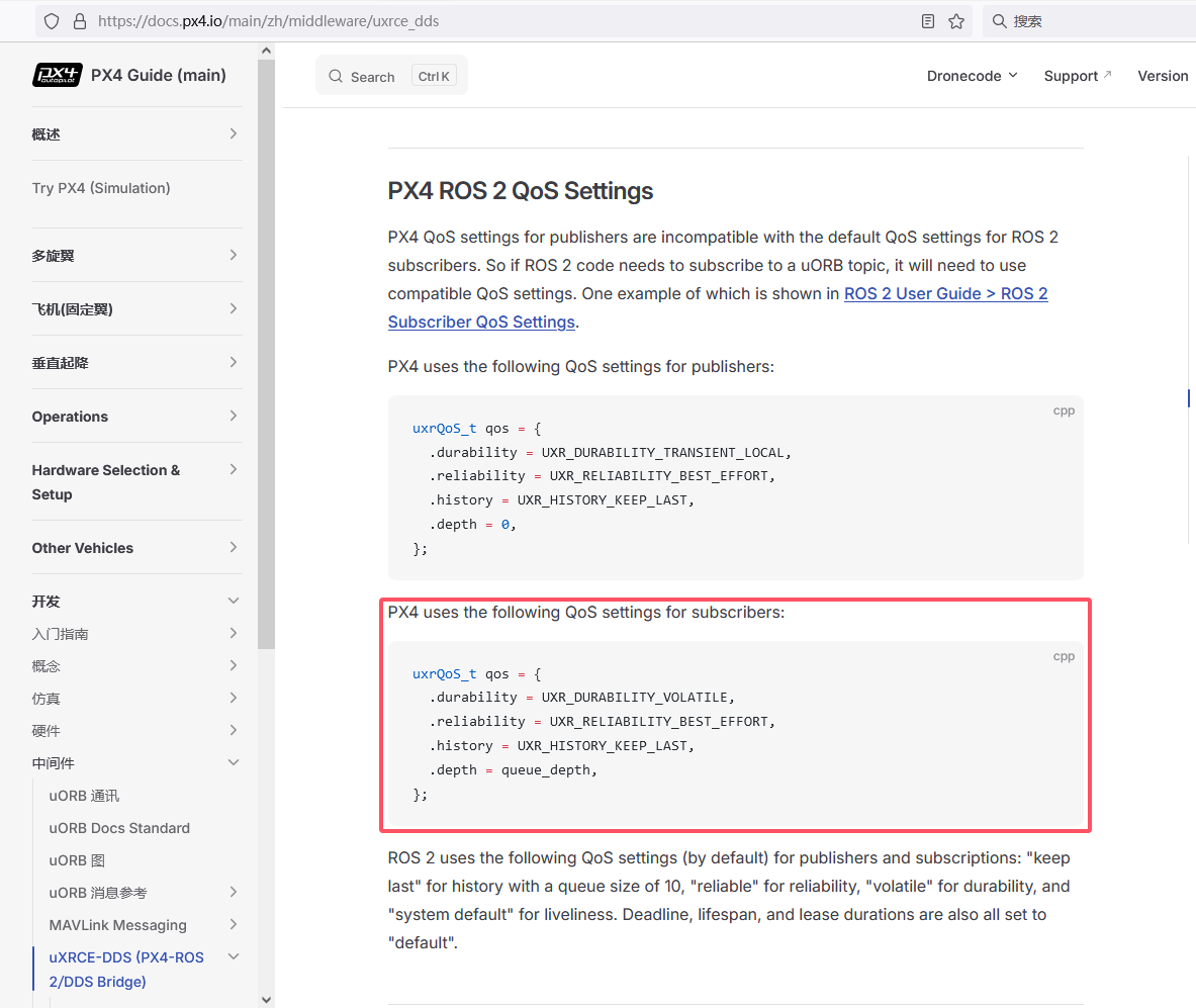
https://docs.px4.io/main/zh/ros2/user_guide#ros-2-%E8%AE%A2%E9%98%85%E8%80%85qos-%E8%AE%BE%E7%BD%AE
从后面给的示例程序也可以看出 https://docs.px4.io/main/zh/ros2/user_guide#ros-2-%E7%A4%BA%E4%BE%8B%E5%BA%94%E7%94%A8%E7%A8%8B%E5%BA%8F
在订阅PX4发布的话题的示例代码sensor_combined_listener.cpp中,该订阅会基于 rmw_qos_profile_sensor_data 设置一个 QoS 配置文件。 之所以需要这样做,是因为 ROS 2 订阅者的默认 QoS(服务质量)配置文件,与 PX4 发布者的配置文件不兼容。
https://github.com/PX4/px4_ros_com/blob/main/src/examples/listeners/sensor_combined_listener.cpp
public:
  explicit SensorCombinedListener() : Node("sensor_combined_listener")
  {
    rmw_qos_profile_t qos_profile = rmw_qos_profile_sensor_data;
    auto qos = rclcpp::QoS(rclcpp::QoSInitialization(qos_profile.history, 5), qos_profile);

    subscription_ = this->create_subscription<px4_msgs::msg::SensorCombined>("/fmu/out/sensor_combined", qos,
    [this](const px4_msgs::msg::SensorCombined::UniquePtr msg) {
      std::cout << "\n\n\n\n\n\n\n\n\n\n\n\n\n\n\n\n\n\n\n\n\n\n\n\n";
      std::cout << "RECEIVED SENSOR COMBINED DATA"   << std::endl;
      std::cout << "============================="   << std::endl;
      std::cout << "ts: "          << msg->timestamp    << std::endl;
      std::cout << "gyro_rad[0]: " << msg->gyro_rad[0]  << std::endl;
      std::cout << "gyro_rad[1]: " << msg->gyro_rad[1]  << std::endl;
      std::cout << "gyro_rad[2]: " << msg->gyro_rad[2]  << std::endl;
      std::cout << "gyro_integral_dt: " << msg->gyro_integral_dt << std::endl;
      std::cout << "accelerometer_timestamp_relative: " << msg->accelerometer_timestamp_relative << std::endl;
      std::cout << "accelerometer_m_s2[0]: " << msg->accelerometer_m_s2[0] << std::endl;
      std::cout << "accelerometer_m_s2[1]: " << msg->accelerometer_m_s2[1] << std::endl;
      std::cout << "accelerometer_m_s2[2]: " << msg->accelerometer_m_s2[2] << std::endl;
      std::cout << "accelerometer_integral_dt: " << msg->accelerometer_integral_dt << std::endl;
    });
  }
而创建一个 ROS 2 发布者节点,将数据发布到 DDS/RTPS 网络中(进而传递给 PX4 飞控)。
以 px4_ros_com/src/advertisers 路径下的 debug_vect_advertiser.cpp(文件)为例,就没有专门设置QoS。
https://github.com/PX4/px4_ros_com/blob/main/src/examples/advertisers/debug_vect_advertiser.cpp
public:
  DebugVectAdvertiser() : Node("debug_vect_advertiser") {
    publisher_ = this->create_publisher<px4_msgs::msg::DebugVect>("fmu/debug_vect/in", 10);
    auto timer_callback =
    [this]()->void {
      auto debug_vect = px4_msgs::msg::DebugVect();
      debug_vect.timestamp = std::chrono::time_point_cast<std::chrono::microseconds>(std::chrono::steady_clock::now()).time_since_epoch().count();
      std::string name = "test";
      std::copy(name.begin(), name.end(), debug_vect.name.begin());
      debug_vect.x = 1.0;
      debug_vect.y = 2.0;
      debug_vect.z = 3.0;
      RCLCPP_INFO(this->get_logger(), "\033[97m Publishing debug_vect: time: %llu x: %f y: %f z: %f \033[0m",
                                    debug_vect.timestamp, debug_vect.x, debug_vect.y, debug_vect.z);
      this->publisher_->publish(debug_vect);
    };
    timer_ = this->create_wall_timer(500ms, timer_callback);
  }

private:
  rclcpp::TimerBase::SharedPtr timer_;
  rclcpp::Publisher<px4_msgs::msg::DebugVect>::SharedPtr publisher_;
};
所以在编写发布 /fmu/in/vehicle_visual_odometry 的 ROS 2 节点时,通常无需手动设置 QoS 参数。
追求保险的话,我们可以做下检查
在启动/fmu/in/vehicle_visual_odometry话题发布节点和Micro XRCE-DDS Agent以及px4飞控后。
在板载计算机上使用ros2 topic info -v /fmu/in/vehicle_visual_odometry查看 QoS 配置
若Publisher Count和Subscription Count都为1,代表已连接,QoS是兼容的,如果Subscription Count是0,说明没有连接成功,QoS有可能不兼容。
Topic: /fmu/in/vehicle_visual_odometry
Topic Type: px4_msgs/msg/VehicleOdometry
Publisher Count: 1
Subscription Count: 1
代码示例
综上,我们可以写出一个把 SLAM 的 nav_msgs/Odometry 或 geometry_msgs/PoseStamped 类型的位姿话题 转成 PX4 的 px4_msgs/VehicleOdometry 类型,发布到 /fmu/in/vehicle_visual_odometry 话题上的ROS2转换节点。
这里以转换基于D435i的imu的双目imu的vinsfusion的位姿话题/vins_estimator/odometry (nav_msgs/Odometry.msg类型)为例,而且注意D435i是水平放置且镜头前方和机头方向一致,即D435i的imu的z轴方向和机头方向一致。
自己可以根据自己实际所用SLAM情况进行对应的调整。
注意功能包内需要包含功能包需要包含px4_msgs(https://github.com/PX4/px4_msgs)
也注意 PX4 的 VehicleOdometry.q 使用 [w, x, y, z] 顺序(与 ROS 的 (x, y, z, w) 不同)
代码中的坐标系变换也是以处理基于D435i的imu的双目imu的vinsfusion的位姿话题为例
因为vinsfusion的位姿话题不输出协方差,所以这里没有在代码里对/fmu/in/vehicle_visual_odometry中的位置和角度的方差赋值。
#include <chrono>
#include <cmath>
#include <algorithm>
#include <iostream>
#include <memory>
#include <string>
#include <limits>  // 用于 std::numeric_limits<double>::quiet_NaN()

#include <rclcpp/rclcpp.hpp>
#include <nav_msgs/msg/odometry.hpp>
#include <px4_msgs/msg/vehicle_odometry.hpp>
#include <Eigen/Dense>
#include <Eigen/Geometry>

using namespace std::chrono_literals;

class slam_to_uxrce_dds : public rclcpp::Node
{
public:
    slam_to_uxrce_dds() : Node("slam_to_uxrce_dds")
    {
        // 1. 初始化变换矩阵T_w_ned和T_frd_b
        //w 重力对齐后的世界系  ned 北东地坐标系  frd 前右下坐标系  b body坐标系(相机系或imu坐标系)
        // T_w_ned
        Eigen::Matrix3d rotation_matrix_w_ned;
        Eigen::Vector3d t_w_ned;
        t_w_ned << 0, 0, 0;
        rotation_matrix_w_ned << -1,  0,  0,
                                  0,  1,  0,
                                  0,  0, -1;
        T_w_ned = Eigen::Isometry3d::Identity();
        T_w_ned.linear() = rotation_matrix_w_ned;
        T_w_ned.translation() = t_w_ned;

        // T_frd_b
        Eigen::Matrix3d rotation_matrix_frd_b;
        Eigen::Vector3d t_frd_b;
        t_frd_b << 0, 0, 0;
        rotation_matrix_frd_b << 0, 1, 0,
                                 0, 0, 1,
                                 1, 0, 0;
        T_frd_b = Eigen::Isometry3d::Identity();
        T_frd_b.linear() = rotation_matrix_frd_b;
        T_frd_b.translation() = t_frd_b;

        // 2. 创建发布者(默认 QoS,队列长度 10)
        publisher_ = this->create_publisher<px4_msgs::msg::VehicleOdometry>(
            "/fmu/in/vehicle_visual_odometry", 10);

        // 3. 创建订阅者:使用 lambda 表达式(无需 std::placeholders::_1)
        subscriber_ = this->create_subscription<nav_msgs::msg::Odometry>(
            "/vins_fusion/odometry", 10,
            [this](const nav_msgs::msg::Odometry::SharedPtr msg) {
                this->odometry_callback(msg);
            });
    }

private:
    void odometry_callback(const nav_msgs::msg::Odometry::SharedPtr msg)
    {
        // 从 SLAM 消息中提取 pose: T_b_w(对于/vins_fusion/odometry而言就是imu坐标系(body系)在重力对齐世界系下的位姿)
        Eigen::Quaterniond q_b_w(
            msg->pose.pose.orientation.w,
            msg->pose.pose.orientation.x,
            msg->pose.pose.orientation.y,
            msg->pose.pose.orientation.z
        );
        Eigen::Vector3d t_b_w(
            msg->pose.pose.position.x,
            msg->pose.pose.position.y,
            msg->pose.pose.position.z
        );

        Eigen::Isometry3d T_b_w = Eigen::Isometry3d::Identity();
        T_b_w.linear() = q_b_w.toRotationMatrix();
        T_b_w.translation() = t_b_w;

        // 坐标系变换:T_frd_ned = T_w_ned * T_b_w * T_frd_b
        Eigen::Isometry3d T_frd_ned = T_w_ned * T_b_w * T_frd_b;

        Eigen::Quaterniond q_frd_ned(T_frd_ned.linear());
        Eigen::Vector3d trans_frd_ned = T_frd_ned.translation();

        // 构造 VehicleOdometry 消息
        auto vo_msg = px4_msgs::msg::VehicleOdometry();

        // 时间戳:把时间戳转为微秒单位,/fmu/in/vehicle_visual_odometry里的时间戳单位是微秒
        uint64_t timestamp_us = static_cast<uint64_t>(msg->header.stamp.sec) * 1000000ULL +
                                static_cast<uint64_t>(msg->header.stamp.nanosec) / 1000ULL;
        vo_msg.timestamp = timestamp_us;
        vo_msg.timestamp_sample = timestamp_us;

        // 帧类型
        vo_msg.pose_frame = px4_msgs::msg::VehicleOdometry::POSE_FRAME_NED;
        vo_msg.velocity_frame = px4_msgs::msg::VehicleOdometry::VELOCITY_FRAME_NED;

        // 位置 (xyz)
        vo_msg.position[0] = trans_frd_ned.x();
        vo_msg.position[1] = trans_frd_ned.y();
        vo_msg.position[2] = trans_frd_ned.z();

        // 四元数 (w, x, y, z)
        vo_msg.q[0] = q_frd_ned.w();
        vo_msg.q[1] = q_frd_ned.x();
        vo_msg.q[2] = q_frd_ned.y();
        vo_msg.q[3] = q_frd_ned.z();

        // NaN 值
        const double nan_val = std::numeric_limits<double>::quiet_NaN();

        vo_msg.velocity[0] = nan_val;
        vo_msg.velocity[1] = nan_val;
        vo_msg.velocity[2] = nan_val;

        vo_msg.angular_velocity[0] = nan_val;
        vo_msg.angular_velocity[1] = nan_val;
        vo_msg.angular_velocity[2] = nan_val;

        vo_msg.position_variance[0] = nan_val;
        vo_msg.position_variance[1] = nan_val;
        vo_msg.position_variance[2] = nan_val;

        vo_msg.orientation_variance[0] = nan_val;
        vo_msg.orientation_variance[1] = nan_val;
        vo_msg.orientation_variance[2] = nan_val;

        vo_msg.velocity_variance[0] = nan_val;
        vo_msg.velocity_variance[1] = nan_val;
        vo_msg.velocity_variance[2] = nan_val;

        vo_msg.reset_counter = 0;
        vo_msg.quality = 0;

        // 调试日志(每秒最多 1 次)
        RCLCPP_INFO_THROTTLE(this->get_logger(), *this->get_clock(), 1000ms,
            "\033[97m Publishing vehicle_visual_odometry: time=%llu x=%.3f y=%.3f z=%.3f \033[0m",
            vo_msg.timestamp, vo_msg.position[0], vo_msg.position[1], vo_msg.position[2]);

        // 发布消息
        publisher_->publish(vo_msg);
    }

    rclcpp::Publisher<px4_msgs::msg::VehicleOdometry>::SharedPtr publisher_;
    rclcpp::Subscription<nav_msgs::msg::Odometry>::SharedPtr subscriber_;

    Eigen::Isometry3d T_w_ned;
    Eigen::Isometry3d T_frd_b;
};

int main(int argc, char *argv[])
{
    std::cout << "Starting slam_to_uxrce_dds ROS 2 node..." << std::endl;
    setvbuf(stdout, NULL, _IONBF, BUFSIZ);
    rclcpp::init(argc, argv);

    rclcpp::spin(std::make_shared<slam_to_uxrce_dds>());

    rclcpp::shutdown();
    return 0;
}
说明: NaN 设置使用 std::numeric_limits::quiet_NaN() 是标准做法。
相关飞控参数设置
https://docs.px4.io/main/zh/advanced_config/parameter_reference
所有和视觉位姿融合相关的飞控参数可见:PX4-Autopilot\src\modules\ekf2\params_external_vision.yaml
- EKF2_EV_CTRL
选择 0: Horizontal position 1: Vertical position 和 3: Yaw ,表示水平位置,垂直位置和偏航用视觉位姿数据
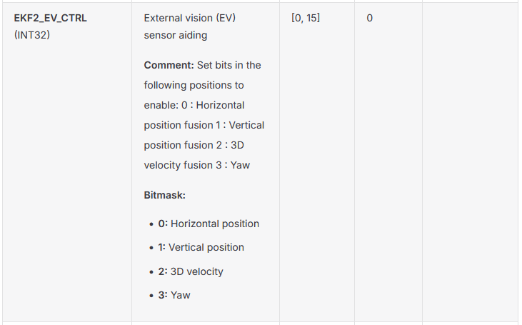
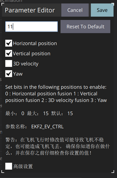
- EKF2_EV_DELAY
如果不太清楚SLAM时延,可以参考这篇文章 借助px4日志简便估计SLAM位姿时延操作方法 https://blog.csdn.net/sinat_16643223/article/details/145396273?spm=1001.2014.3001.5502
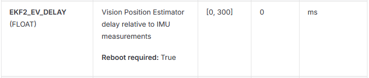
- EKF2_EV_NOISE_MD(需要确认)
EKF2_EV_NOISE_MD(Noise Mode)用于选择外部视觉(External Vision)观测噪声的来源,即决定 EKF2 在融合vehicle_visual_odometry时使用消息中自带的协方差,还是使用参数中设定的固定噪声。
| 值 | 名称 | 含义 |
|---|---|---|
| 0(默认) | EV Pos/Vel/Yaw uses EV noise | 使用消息自带的协方差(来自 VehicleOdometry 的 variance 字段),但参数值会作为下限,也就是协方差始终不会低于EKF2_EVx_NOISE²,防止外部估计器过度自信(R = max(消息方差, 参数²)) |
| 1 | EV Pos/Vel/Yaw uses param noise | 忽略消息里的 position_variance / velocity_variance / orientation_variance,强制使用参数 EKF2_EVP_NOISE、EKF2_EVV_NOISE、EKF2_EVA_NOISE 作为观测噪声 |
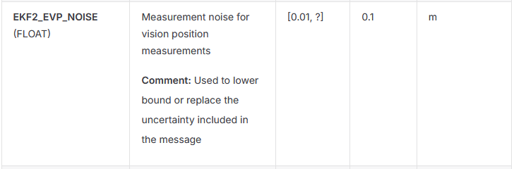
- EKF2_EVP_NOISE
注意飞控参数EKF2_EVx_NOISE中设置的值是没有平方之前的数,不是平方之后的数。
具体设置参考上面协方差赋值一节
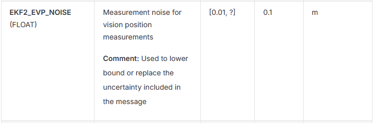
-
EKF2_EVA_NOISE
一般用默认值0.1就行,不用特别改动,可以检查确认一下,主要可能影响视觉偏航的融合 -
UXRCE_DDS_SYNCT(需要确认)
默认置1,启动时间同步
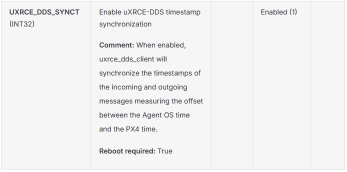
Micro XRCE-DDS 串口相关参数
- UXRCE_DDS_CFG
选择为飞控和板载计算机进行通信的串口,同时对应串口波特率也需要确认
使用对应串口的 _BAUD 参数设置波特率。例如,若通过 TELEM2 连接 companion 计算机,则需配置 SER_TEL2_BAUD。
多数串口已预设默认配置。如需复用这些端口,必须先禁用原有配置:
TELEM1 和 TELEM2 默认分别通过 MAVLink 连接 GCS 与 companion 计算机;可通过将 MAV_0_CONFIG=0 或 MAV_1_CONFIG=0 禁用。
PX4的串口配置可以看 https://docs.px4.io/main/zh/peripherals/serial_configuration#serial-port-configuration
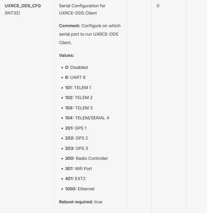
检查确认
在 QGroundControl 的 MAVLink Console 中运行:
listener vehicle_visual_odometry
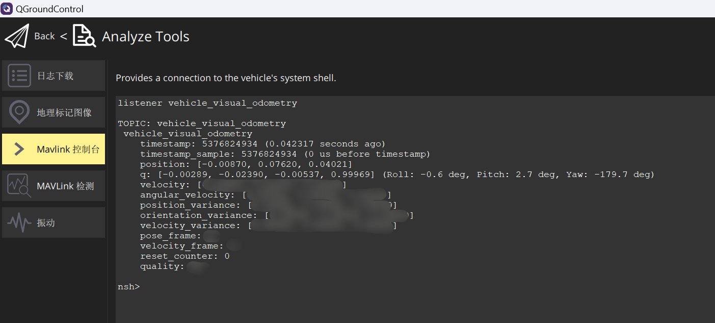
若看到持续更新的输出,说明消息已成功从 /fmu/in/vehicle_visual_odometry → Micro XRCE-DDS Agent → uxrce_dds_client(PX4) → vehicle_visual_odometry(uORB)。
ROS端打印/fmu/out/vehicle_local_position,和/fmu/in/vehicle_visual_odometry进行对比,可以同时手拿着移动无人机,如果两者位姿基本一致,说明PX4飞控已经将视觉位姿融合进来了。
ros2 topic echo /fmu/out/vehicle_local_position
这么检查都没有问题后,可以遥控器切定点,从地面站看PX4飞控是否切到了position模式,切到定点模式后,可以尝试解锁起飞。
参考资料
https://docs.px4.io/main/zh/ros2/user_guide
https://docs.px4.io/main/zh/middleware/uxrce_dds
https://github.com/PX4/PX4-Autopilot/blob/main/src/modules/uxrce_dds_client
https://github.com/PX4/px4_ros_com
https://fishros.org.cn/forum/topic/1757/ros2%E9%80%9A%E8%AE%AF%E6%9C%8D%E5%8A%A1%E8%B4%A8%E9%87%8Fqos%E4%BB%8B%E7%BB%8D%E4%B8%8E%E6%A0%B7%E4%BE%8B
https://blog.csdn.net/m0_67254825/article/details/148825941?spm=1001.2014.3001.5506
本文所涉及的PX4代码和PX4文档是目前PX4 main分支最新代码( https://github.com/PX4/PX4-Autopilot/tree/8ddbedf8686550480b6d735d509b360e5abbed0c )及main分支对应文档https://docs.px4.io/main/zh/

免费领 150 小时云算力,进群参与显卡、AI PC 幸运抽奖
更多推荐



 6
6 0
0- 0


 已为社区贡献1条内容

所有评论(0)