
土木本科生的STM32探索之旅:ADC+阻塞式采集外接光敏电阻的阻值,并usart串口将数据发送到电脑串口助手
·
在上一篇文章中,我们已经有实现了ADC+DMA采集光敏电阻阻值的情况,但采集的结果也有待一定的验证其准确性。本期文章将使用另外一种方式采集采集光敏电阻阻值,最后的实验结果我利用小电筒验证过了,符合物理定律。
废话不多说,下面我就直接开始演示实验的操作。(实验已经跑过了,为了方便就在下方粘贴图片和代码了哦)
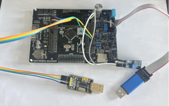
usb转ttl、光敏电阻、st-link及stm32f103vet6
基于deepseek专家模式下的实验
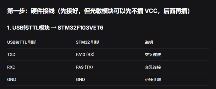
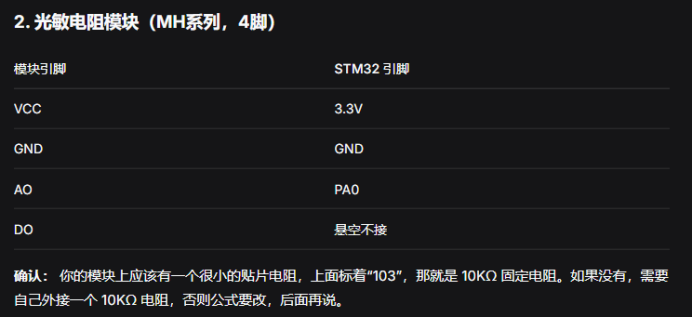
光敏电阻上面有一个蓝色方形的小玩意,写了p103。(蓝色方形小元件是贴片电阻,上面的P103表示10,000Ω = 10KΩ)。蓝色方形P103:光敏模块的10KΩ分压电阻。
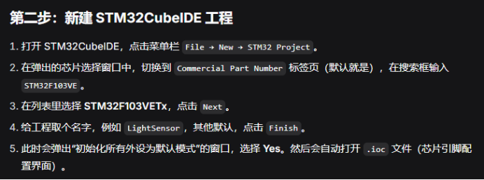
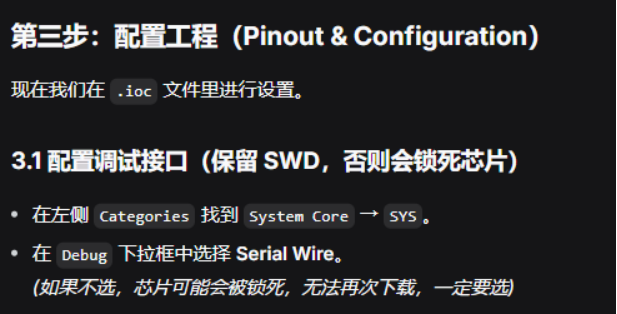
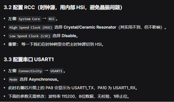
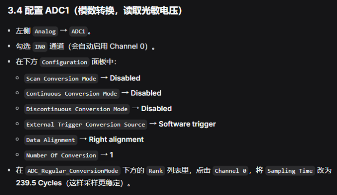
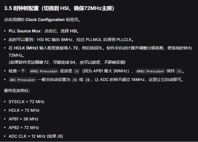
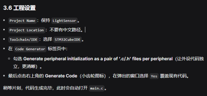
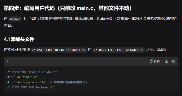
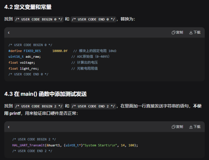
4.4 while循环
  /* Infinite loop */
  /* USER CODE BEGIN WHILE */
  while (1)
  {
    /* USER CODE END WHILE */

    /* USER CODE BEGIN 3 */

    // 1. 启动ADC转换
    HAL_ADC_Start(&hadc1);

    // 2. 等待转换完成,超时100ms
    if (HAL_ADC_PollForConversion(&hadc1, 100) == HAL_OK)
    {
        // 3. 读取ADC原始值
        adc_raw = HAL_ADC_GetValue(&hadc1);

        // 4. 计算电压 (参考电压3.3V)
        voltage = adc_raw * 3.3f / 4095.0f;

        // 5. 计算光敏电阻阻值(固定电阻在上臂,光敏电阻在下臂)
        // 推导公式:Vout = 3.3 * R_ldr / (R_fixed + R_ldr)
        //  => R_ldr = (Vout * R_fixed) / (3.3 - Vout)
        if ((3.3f - voltage) > 0.05f)
        {
            light_res = voltage * FIXED_RES / (3.3f - voltage);
        }
        else
        {
            light_res = 999999.0f;   // 电压接近3.3V,光线极暗,阻值极大
        }

        // 6. 通过printf打印到串口
        printf("ADC:%d, Voltage:%.2fV, LightRes:%.0f ohm\r\n",
               adc_raw, voltage, light_res);
    }

    // 7. 停止ADC(单次转换模式需要停止)
    HAL_ADC_Stop(&hadc1);

    // 延时500ms,防止刷屏太快
    HAL_Delay(500);

    /* USER CODE END 3 */
  }
  /* USER CODE END WHILE */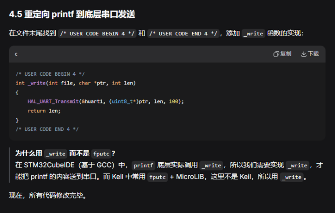
整个main.c代码如下:
/* USER CODE BEGIN Header */
/**
******************************************************************************
* @file : main.c
* @brief : Main program body
******************************************************************************
* @attention
*
* Copyright (c) 2026 STMicroelectronics.
* All rights reserved.
*
* This software is licensed under terms that can be found in the LICENSE file
* in the root directory of this software component.
* If no LICENSE file comes with this software, it is provided AS-IS.
*
******************************************************************************
*/
/* USER CODE END Header */
/* Includes ------------------------------------------------------------------*/
#include "main.h"

/* Private includes ----------------------------------------------------------*/
/* USER CODE BEGIN Includes */
#include "stdio.h"
#include <sys/unistd.h> // 如果编译错误可删除此行
/* USER CODE END Includes */

/* Private typedef -----------------------------------------------------------*/
/* USER CODE BEGIN PTD */

/* USER CODE END PTD */

/* Private define ------------------------------------------------------------*/
/* USER CODE BEGIN PD */

/* USER CODE END PD */

/* Private macro -------------------------------------------------------------*/
/* USER CODE BEGIN PM */

/* USER CODE END PM */

/* Private variables ---------------------------------------------------------*/
ADC_HandleTypeDef hadc1;

UART_HandleTypeDef huart1;

/* USER CODE BEGIN PV */

/* USER CODE END PV */

/* Private function prototypes -----------------------------------------------*/
void SystemClock_Config(void);
static void MX_GPIO_Init(void);
static void MX_ADC1_Init(void);
static void MX_USART1_UART_Init(void);
/* USER CODE BEGIN PFP */

/* USER CODE END PFP */

/* Private user code ---------------------------------------------------------*/
/* USER CODE BEGIN 0 */
#define FIXED_RES 10000.0f // 模块上的固定电阻 10kΩ
uint16_t adc_raw; // ADC原始值(0-4095)
float voltage; // 计算出的电压
float light_res; // 光敏电阻阻值
/* USER CODE END 0 */

/**
* @brief The application entry point.
* @retval int
*/
int main(void)
{

/* USER CODE BEGIN 1 */

/* USER CODE END 1 */

/* MCU Configuration--------------------------------------------------------*/

/* Reset of all peripherals, Initializes the Flash interface and the Systick. */
HAL_Init();

/* USER CODE BEGIN Init */

/* USER CODE END Init */

/* Configure the system clock */
SystemClock_Config();

/* USER CODE BEGIN SysInit */

/* USER CODE END SysInit */

/* Initialize all configured peripherals */
MX_GPIO_Init();
MX_ADC1_Init();
MX_USART1_UART_Init();
/* USER CODE BEGIN 2 */
HAL_UART_Transmit(&huart1, (uint8_t*)"System Start\r\n", 14, 100);
/* USER CODE END 2 */

/* Infinite loop */
/* USER CODE BEGIN WHILE */
while (1)
{
/* USER CODE END WHILE */

/* USER CODE BEGIN 3 */

// 1. 启动ADC转换
HAL_ADC_Start(&hadc1);

// 2. 等待转换完成,超时100ms
if (HAL_ADC_PollForConversion(&hadc1, 100) == HAL_OK)
{
// 3. 读取ADC原始值
adc_raw = HAL_ADC_GetValue(&hadc1);

// 4. 计算电压 (参考电压3.3V)
voltage = adc_raw * 3.3f / 4095.0f;

// 5. 计算光敏电阻阻值(固定电阻在上臂,光敏电阻在下臂)
// 推导公式:Vout = 3.3 * R_ldr / (R_fixed + R_ldr)
// => R_ldr = (Vout * R_fixed) / (3.3 - Vout)
if ((3.3f - voltage) > 0.05f)
{
light_res = voltage * FIXED_RES / (3.3f - voltage);
}
else
{
light_res = 999999.0f; // 电压接近3.3V,光线极暗,阻值极大
}

// 6. 通过printf打印到串口
printf("ADC:%d, Voltage:%.2fV, LightRes:%.0f ohm\r\n",
adc_raw, voltage, light_res);
}

// 7. 停止ADC(单次转换模式需要停止)
HAL_ADC_Stop(&hadc1);

// 延时500ms
HAL_Delay(500);

}
/* USER CODE END 3 */
}

/**
* @brief System Clock Configuration
* @retval None
*/
void SystemClock_Config(void)
{
RCC_OscInitTypeDef RCC_OscInitStruct = {0};
RCC_ClkInitTypeDef RCC_ClkInitStruct = {0};
RCC_PeriphCLKInitTypeDef PeriphClkInit = {0};

/** Initializes the RCC Oscillators according to the specified parameters
* in the RCC_OscInitTypeDef structure.
*/
RCC_OscInitStruct.OscillatorType = RCC_OSCILLATORTYPE_HSE;
RCC_OscInitStruct.HSEState = RCC_HSE_ON;
RCC_OscInitStruct.HSEPredivValue = RCC_HSE_PREDIV_DIV1;
RCC_OscInitStruct.HSIState = RCC_HSI_ON;
RCC_OscInitStruct.PLL.PLLState = RCC_PLL_ON;
RCC_OscInitStruct.PLL.PLLSource = RCC_PLLSOURCE_HSE;
RCC_OscInitStruct.PLL.PLLMUL = RCC_PLL_MUL9;
if (HAL_RCC_OscConfig(&RCC_OscInitStruct) != HAL_OK)
{
Error_Handler();
}

/** Initializes the CPU, AHB and APB buses clocks
*/
RCC_ClkInitStruct.ClockType = RCC_CLOCKTYPE_HCLK|RCC_CLOCKTYPE_SYSCLK
|RCC_CLOCKTYPE_PCLK1|RCC_CLOCKTYPE_PCLK2;
RCC_ClkInitStruct.SYSCLKSource = RCC_SYSCLKSOURCE_PLLCLK;
RCC_ClkInitStruct.AHBCLKDivider = RCC_SYSCLK_DIV1;
RCC_ClkInitStruct.APB1CLKDivider = RCC_HCLK_DIV2;
RCC_ClkInitStruct.APB2CLKDivider = RCC_HCLK_DIV1;

if (HAL_RCC_ClockConfig(&RCC_ClkInitStruct, FLASH_LATENCY_2) != HAL_OK)
{
Error_Handler();
}
PeriphClkInit.PeriphClockSelection = RCC_PERIPHCLK_ADC;
PeriphClkInit.AdcClockSelection = RCC_ADCPCLK2_DIV6;
if (HAL_RCCEx_PeriphCLKConfig(&PeriphClkInit) != HAL_OK)
{
Error_Handler();
}
}

/**
* @brief ADC1 Initialization Function
* @param None
* @retval None
*/
static void MX_ADC1_Init(void)
{

/* USER CODE BEGIN ADC1_Init 0 */

/* USER CODE END ADC1_Init 0 */

ADC_ChannelConfTypeDef sConfig = {0};

/* USER CODE BEGIN ADC1_Init 1 */

/* USER CODE END ADC1_Init 1 */

/** Common config
*/
hadc1.Instance = ADC1;
hadc1.Init.ScanConvMode = ADC_SCAN_DISABLE;
hadc1.Init.ContinuousConvMode = DISABLE;
hadc1.Init.DiscontinuousConvMode = DISABLE;
hadc1.Init.ExternalTrigConv = ADC_SOFTWARE_START;
hadc1.Init.DataAlign = ADC_DATAALIGN_RIGHT;
hadc1.Init.NbrOfConversion = 1;
if (HAL_ADC_Init(&hadc1) != HAL_OK)
{
Error_Handler();
}

/** Configure Regular Channel
*/
sConfig.Channel = ADC_CHANNEL_0;
sConfig.Rank = ADC_REGULAR_RANK_1;
sConfig.SamplingTime = ADC_SAMPLETIME_239CYCLES_5;
if (HAL_ADC_ConfigChannel(&hadc1, &sConfig) != HAL_OK)
{
Error_Handler();
}
/* USER CODE BEGIN ADC1_Init 2 */

/* USER CODE END ADC1_Init 2 */

}

/**
* @brief USART1 Initialization Function
* @param None
* @retval None
*/
static void MX_USART1_UART_Init(void)
{

/* USER CODE BEGIN USART1_Init 0 */

/* USER CODE END USART1_Init 0 */

/* USER CODE BEGIN USART1_Init 1 */

/* USER CODE END USART1_Init 1 */
huart1.Instance = USART1;
huart1.Init.BaudRate = 115200;
huart1.Init.WordLength = UART_WORDLENGTH_8B;
huart1.Init.StopBits = UART_STOPBITS_1;
huart1.Init.Parity = UART_PARITY_NONE;
huart1.Init.Mode = UART_MODE_TX_RX;
huart1.Init.HwFlowCtl = UART_HWCONTROL_NONE;
huart1.Init.OverSampling = UART_OVERSAMPLING_16;
if (HAL_UART_Init(&huart1) != HAL_OK)
{
Error_Handler();
}
/* USER CODE BEGIN USART1_Init 2 */

/* USER CODE END USART1_Init 2 */

}

/**
* @brief GPIO Initialization Function
* @param None
* @retval None
*/
static void MX_GPIO_Init(void)
{
/* USER CODE BEGIN MX_GPIO_Init_1 */
/* USER CODE END MX_GPIO_Init_1 */

/* GPIO Ports Clock Enable */
__HAL_RCC_GPIOA_CLK_ENABLE();

/* USER CODE BEGIN MX_GPIO_Init_2 */
/* USER CODE END MX_GPIO_Init_2 */
}

/* USER CODE BEGIN 4 */
int _write(int file, char *ptr, int len)
{
HAL_UART_Transmit(&huart1, (uint8_t*)ptr, len, 100);
return len;
}
/* USER CODE END 4 */

/**
* @brief This function is executed in case of error occurrence.
* @retval None
*/
void Error_Handler(void)
{
/* USER CODE BEGIN Error_Handler_Debug */
/* User can add his own implementation to report the HAL error return state */
__disable_irq();
while (1)
{
}
/* USER CODE END Error_Handler_Debug */
}

#ifdef USE_FULL_ASSERT
/**
* @brief Reports the name of the source file and the source line number
* where the assert_param error has occurred.
* @param file: pointer to the source file name
* @param line: assert_param error line source number
* @retval None
*/
void assert_failed(uint8_t *file, uint32_t line)
{
/* USER CODE BEGIN 6 */
/* User can add his own implementation to report the file name and line number,
ex: printf("Wrong parameters value: file %s on line %d\r\n", file, line) */
/* USER CODE END 6 */
}
#endif /* USE_FULL_ASSERT */
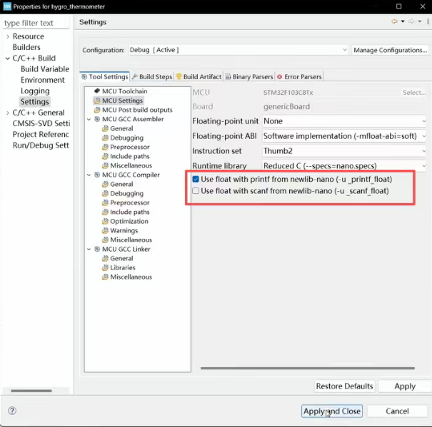
有需要的话可能需要在设置里面打开浮点,怎么打开可以参考下面视频连接。
大概是在5分钟的样子,博主会讲述怎么打开浮点,勾选下面红色框框的就好了。
无遮挡的情况:
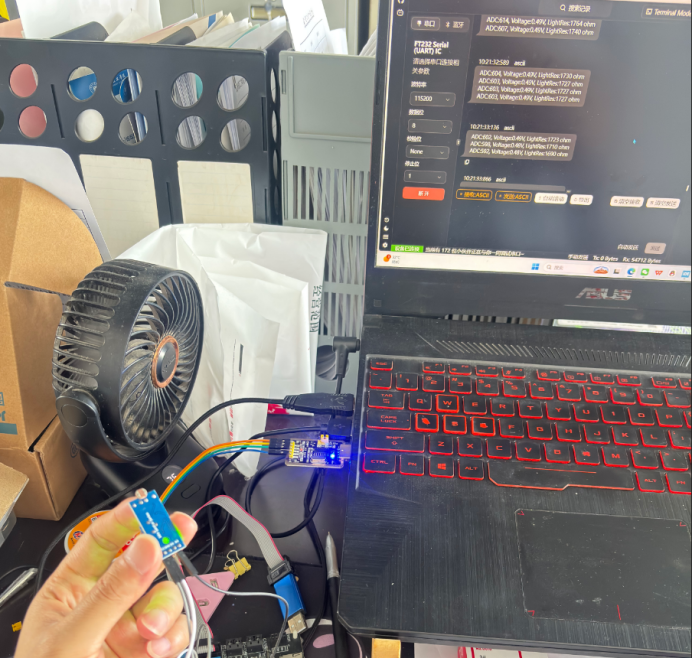
遮挡住以后的情况:
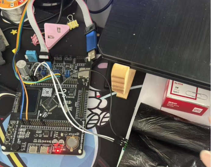
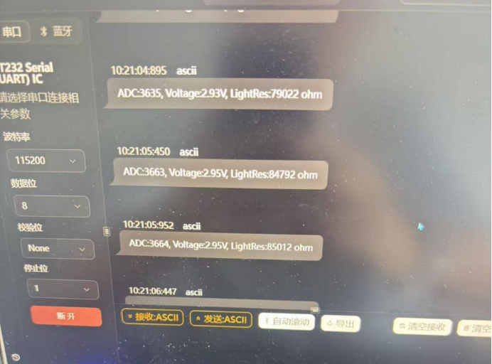
我用手机手电筒打在光敏电阻上面,输出的结果如下:
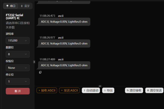 ADC:0, Voltage:0.00V, LightRes:0 ohm
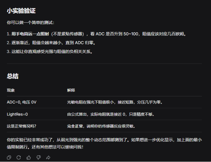
- 手电直射 → ADC=0,电阻 = 0Ω(强光)
- 手电远离 → ADC 变大,电阻变大(弱光)
有对此类实验结果有疑惑的小伙伴可以帮我再验证验证,欢迎大家一块学习,有不对的地方请赐教哦

免费领 150 小时云算力,进群参与显卡、AI PC 幸运抽奖
更多推荐

 6
6 0
0- 0


 已为社区贡献2条内容

所有评论(0)