huawei 华为 交换机 配置 Dot1q 终结子接口实现跨设备 VLAN 间通信示例
huawei 华为 交换机 配置 Dot1q 终结子接口实现跨设备 VLAN 间通信示例
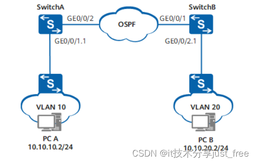
组网需求
如图7-8所示,SwitchA和SwitchB分别下挂VLAN 10和VLAN 20的二层网络,SwitchA和SwitchB之间通过三层网络互通,三层网络采用OSPF协议。要求两个二层网络的PC实现二层隔离三层互通。
图 7-8 配置 Dot1q 终结子接口实现跨设备 VLAN 间通信示例组网图

配置思路
采用如下的思路配置通过子接口跨越三层网络通信:
1. 配置接口所属的VLAN。
2. 配置VLANIF接口的IP地址。
3. 配置子接口的封装方式。
4. 配置子接口允许通过的VLAN。
5. 配置子接口的IP地址。
6. 配置OSPF基本功能。
说明:
- 子接口允许通过的VLAN不能在全局创建。
- VCMP的角色是Client时,不能配置VLAN终结子接口。
操作步骤
步骤1 配置SwitchA
# 创建VLAN。
<HUAWEI> system-view
[HUAWEI] sysname SwitchA
[SwitchA] vlan batch 30
# 配置接口加入VLAN。
[SwitchA] interface gigabitethernet 0/0/2
[SwitchA-GigabitEthernet0/0/2] port link-type trunk
[SwitchA-GigabitEthernet0/0/2] port trunk allow-pass vlan 30
[SwitchA-GigabitEthernet0/0/2] quit
# 配置VLANIF接口的IP地址。
[SwitchA] interface vlanif 30
[SwitchA-Vlanif30] ip address 10.10.30.1 24
[SwitchA-Vlanif30] quit
# 创建并配置子接口GE0/0/1.1。
[SwitchA] vcmp role silent
[SwitchA] interface gigabitethernet0/0/1
[SwitchA-GigabitEthernet0/0/1] port link-type hybrid
[SwitchA-GigabitEthernet0/0/1] quit
[SwitchA] interface gigabitethernet 0/0/1.1
[SwitchA-GigabitEthernet0/0/1.1] dot1q termination vid 10
[SwitchA-GigabitEthernet0/0/1.1] ip address 10.10.10.1 24
[SwitchA-GigabitEthernet0/0/1.1] arp broadcast enable
[SwitchA-GigabitEthernet0/0/1.1] quit
# 配置OSPF基本功能。
[SwitchA] router id 1.1.1.1
[SwitchA] ospf
[SwitchA-ospf-1] area 0
[SwitchA-ospf-1-area-0.0.0.0] network 10.10.10.0 0.0.0.255
[SwitchA-ospf-1-area-0.0.0.0] network 10.10.30.0 0.0.0.255
[SwitchA-ospf-1-area-0.0.0.0] return
步骤2 配置SwitchB
# 创建VLAN。
<HUAWEI> system-view
[HUAWEI] sysname SwitchB
[SwitchB] vlan batch 30
# 配置接口加入VLAN。
[SwitchB] interface gigabitethernet 0/0/1
[SwitchB-GigabitEthernet0/0/1] port link-type trunk
[SwitchB-GigabitEthernet0/0/1] port trunk allow-pass vlan 30
[SwitchB-GigabitEthernet0/0/1] quit
# 配置VLANIF接口的IP地址。
[SwitchB] interface vlanif 30
[SwitchB-Vlanif30] ip address 10.10.30.2 24
[SwitchB-Vlanif30] quit
# 创建并配置子接口GE0/0/2.1。
[SwitchB] vcmp role silent
[SwitchB] interface gigabitethernet0/0/2
[SwitchB-GigabitEthernet0/0/2] port link-type hybrid
[SwitchB-GigabitEthernet0/0/2] quit
[SwitchB] interface gigabitethernet 0/0/2.1
[SwitchB-GigabitEthernet0/0/2.1] dot1q termination vid 20
[SwitchB-GigabitEthernet0/0/2.1] ip address 10.10.20.1 24
[SwitchB-GigabitEthernet0/0/2.1] arp broadcast enable
[SwitchB-GigabitEthernet0/0/2.1] quit
# 配置OSPF基本功能。
[SwitchB] router id 2.2.2.2
[SwitchB] ospf
[SwitchB-ospf-1] area 0
[SwitchB-ospf-1-area-0.0.0.0] network 10.10.20.0 0.0.0.255
[SwitchB-ospf-1-area-0.0.0.0] network 10.10.30.0 0.0.0.255
[SwitchB-ospf-1-area-0.0.0.0] return
步骤3 检查配置结果
SwitchA下挂的二层网络中PC上配置缺省网关为GE0/0/1.1接口的IP地址
10.10.10.1/24。SwitchA下挂的交换机允许VLAN 10通过。
SwitchB下挂的二层网络中PC上配置缺省网关为GE0/0/2.1接口的IP地址
10.10.20.1/24。SwitchB下挂的交换机允许VLAN 20通过。
配置完成后,两个二层网络的PC实现二层隔离三层互通。
----结束
配置文件
SwitchA的配置文件
#
sysname SwitchA
#
router id 1.1.1.1
#
vlan batch 30
#
interface Vlanif30
ip address 10.10.30.1 255.255.255.0
#
interface GigabitEthernet0/0/1
port link-type hybrid
#
interface GigabitEthernet0/0/1.1
dot1q termination vid 10
ip address 10.10.10.1 255.255.255.0
arp broadcast enable
#
interface GigabitEthernet0/0/2
port link-type trunk
port trunk allow-pass vlan 30
#
ospf 1
area 0.0.0.0
network 10.10.10.0 0.0.0.255
network 10.10.30.0 0.0.0.255
#
return
SwitchB的配置文件
#
sysname SwitchB
#
router id 2.2.2.2
#
vlan batch 30
#
interface Vlanif30
ip address 10.10.30.2 255.255.255.0
#
interface GigabitEthernet0/0/1
port link-type trunk
port trunk allow-pass vlan 30
#
interface GigabitEthernet0/0/2
port link-type hybrid
#
interface GigabitEthernet0/0/2.1
dot1q termination vid 20
ip address 10.10.20.1 255.255.255.0
arp broadcast enable
#
ospf 1
area 0.0.0.0
network 10.10.20.0 0.0.0.255
network 10.10.30.0 0.0.0.255
#
return

欢迎加入西安开发者社区!我们致力于为西安地区的开发者提供学习、合作和成长的机会。参与我们的活动,与专家分享最新技术趋势,解决挑战,探索创新。加入我们,共同打造技术社区!
更多推荐


 11
11 0
0- 0


 已为社区贡献1条内容

所有评论(0)