
【Cadence】stb仿真
相关知识链接:
Cadence ADE 中如何实现特定时刻的 AC/STB 仿真
运算放大器stb仿真与闭环增益备忘
运算放大器仿真方式记录
stb仿真原理
by keeping the loop closed for the DC analysis and opening it for AC; this has problems with correctly taking the loading into account.
it injects a signal at the probe point and measures it returning around the loop.The stb analysis is geared up for when you have a DC operating point and then does a small signal analysis around that. ||For a switching circuit, you’re more likely to need to analyse a period of operation of the circuit and use this time-varying operating point to analyse the time-averaged stability using pstb.
pstb和stb都不会“打破回路”(这是模拟稳定性的传统方法,通过保持回路闭合的直流分析和开路的交流分析。它在探测点注入一个信号,然后测量它返回到循环中。stb分析是为了当你有一个直流工作点,然后做一个小信号分析。对于一个开关电路,你更可能需要分析电路运行的一段时间,并使用这个时变工作点来分析使用pstb的时间平均稳定性。
If the loop is not closed, you can use pss + pac analysis (or pss + pxf analysis).
because we are in the presence of a time-arying circuit with non-linear components (Switches),the authors from the books I referred had modeled the switches in such a way so that they could become linear and from there be inserted into the overall converter to be simulated.
对于一些时变电路,由于没有固定的稳态工作点,因此无法直接对其进行交流(AC)或环路稳定性(STB)仿真分析。此时,常用的方法是利用 PSS 分析找到电路的周期稳态,再用 PAC 或 PSTB 来分析等效的交流特性或环路的稳定性。|| 但 PSS 的周期稳态求解过程常常需要比较多的迭代时间,与此同时,有时我们仅仅需要的是电路某时刻的特性,因此可以考虑在 Cadence ADE 中直接用 tran+ac/stb 的方式来实现特定时刻的 ac/stb 仿真
stb仿真方法
probe:电压源/iprobe/diffprobe等都可以

diffstbprobe和cmdmprobe用法实际上是相同的,无非前者在stb或pstb仿真设置里选择差分或共模,后者在器件上用-1或1来设置差分或共模。关键还在于断开环路插入probe的位置有否问题。如果仅仅仿真差模反馈的话只要从差分输出到差分反馈点之间的所有反馈断开并插入probe器件并设置为差分模式即可。
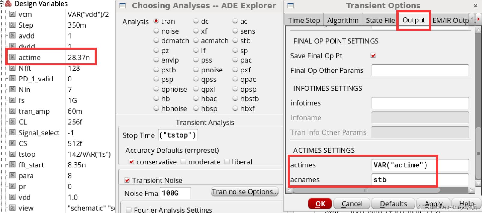
首先,在tran中设置在哪一个时间点进行stb仿真。这个点的选取和spectrumMeasurement类似,都在放大相位快结束的时候。

actimes=[…] s–Times when analyses specified in acname array are performed.
acnames=[…]–Names of ac, noise, sp, stb, or xf analyses to be performed at each time point in the actimes array. The named small-signal analyses are not run separately, but only as part of the transient analysis.
翻译:
actimes =[…s——执行acname数组中指定的分析的时间。
acnames =[…——actimes数组中每个时间点执行的ac、noise、sp、stb或xf分析的名称。命名的小信号分析不单独运行,而只是作为瞬态分析的一部分。
stb仿真需要重点检查的地方
- tran仿真是否放在stb仿真前面。如果stb仿真没结果,一直报错,就需要把tran放在stb上面。
- actime一定要在放大相位快结束的时候
- 注意Nfft和tstop的设置,以及Output中spectrum的设置是否和1G的采样率对的上,只要采样率、采样点数、采样时间变化,则spectrum中snr,sfdr等的设置就要改变。
- 跑PhaseMargin的时候需要关掉噪声,这时候跑出来的spectrum的snr和sfdr是比开噪声大的,但是意义不大。因此跑snr,sfdr的时候要开噪声。
Pss+Pstb/Pac
不能单独使用pstb。如pac, pnoise, pxf等,它要求通过pss分析找到“周期工作点”。pss分析捕获了由大信号周期源引起的非线性,然后pac/pxf/pnoise/pstb分析执行了该周期工作点附近的小信号分析。因此,它将包括来自完整切换周期的信息。然而,它仍在关注小信号的稳定性。

pstb analysis examines sideband 0, so it can only be used if you have an unmodulated signal somewhere in the loop (like for example in switched-mode power supplies).PSTB分析检查边带0,所以只有在回路中某处有未调制信号时才可以使用(例如在开关模式电源中)。
For your pac analysis, I suggest you use sampled pac, so you don’t need the additional ideal S/H.
开关电容电路利用stb仿真得到的仿真结果:

增益曲线:低频下增益下降是因为输入信号经隔直电容
相频曲线:一般从0或-180°开始而这里从-90°开始是因为仿真器的问题,我们看的时候从-180°的相位开始看即可(中频部分)


旨在为数千万中国开发者提供一个无缝且高效的云端环境,以支持学习、使用和贡献开源项目。
更多推荐


 12
12 0
0- 0


 已为社区贡献5条内容

所有评论(0)