
ESP8266之micorpython篇(2)---快速入门开发
注:对于ESP8266开源技术感兴趣的可以加群,我们一起探索交流学习,群号:579932824。群名:ESP8266开源技术交流群。ESP8266的快速参考Adafruit Feather HUZZAH板(图片属性:Adafruit)。安装MicroPython请参阅教程的相应部分:我的上一篇博文教程。一般Board板控制MicroPython REPL位于波特率115...
注:对于ESP8266开源技术感兴趣的可以加群,我们一起探索交流学习,群号:579932824。群名:ESP8266开源技术交流群。
ESP8266的快速参考
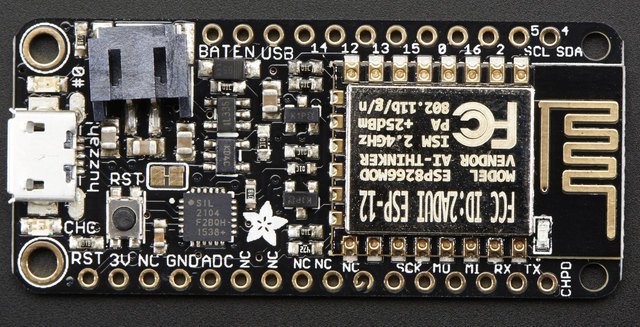
Adafruit Feather HUZZAH板(图片属性:Adafruit)。
安装MicroPython
请参阅教程的相应部分:我的上一篇博文教程。
一般Board板控制
MicroPython REPL位于波特率115200的UART0(GPIO1 = TX,GPIO3 = RX)上。Tab-completion 有助于找出对象具有的方法。粘贴模式(ctrl-E)可用于将大量Python代码粘贴到REPL中。
内置machine模块:
import machine

machine.freq()          # get the current frequency of the CPU
machine.freq(160000000) # set the CPU frequency to 160 MHz
内置esp模块:
import esp

esp.osdebug(None)       # turn off vendor O/S debugging messages
esp.osdebug(0)          # redirect vendor O/S debugging messages to UART(0)
联网
network模块:
import network

wlan = network.WLAN(network.STA_IF) # create station interface
wlan.active(True)       # activate the interface
wlan.scan()             # scan for access points
wlan.isconnected()      # check if the station is connected to an AP
wlan.connect('essid', 'password') # connect to an AP
wlan.config('mac')      # get the interface's MAC adddress
wlan.ifconfig()         # get the interface's IP/netmask/gw/DNS addresses

ap = network.WLAN(network.AP_IF) # create access-point interface
ap.active(True)         # activate the interface
ap.config(essid='ESP-AP') # set the ESSID of the access point
连接到本地WiFi网络的功能函数是:
def do_connect():
    import network
    wlan = network.WLAN(network.STA_IF)
    wlan.active(True)
    if not wlan.isconnected():
        print('connecting to network...')
        wlan.connect('essid', 'password')
        while not wlan.isconnected():
            pass
print('network config:', wlan.ifconfig())一旦建立了网络,该socket模块就可以像往常一样用于创建和使用TCP / UDP套接字。
延迟和时间
使用time模块:
import time

time.sleep(1)           # sleep for 1 second
time.sleep_ms(500)      # sleep for 500 milliseconds
time.sleep_us(10)       # sleep for 10 microseconds
start = time.ticks_ms() # get millisecond counter
delta = time.ticks_diff(time.ticks_ms(), start) # compute time difference
计时器
支持虚拟(基于RTOS)的计时器。使用计时器ID为-1 的machine.Timer类:
from machine import Timer

tim = Timer(-1)
tim.init(period=5000, mode=Timer.ONE_SHOT, callback=lambda t:print(1))
tim.init(period=2000, mode=Timer.PERIODIC, callback=lambda t:print(2))
周期以毫秒为单位。
引脚GPIO
使用machine.Pin类:
from machine import Pin

p0 = Pin(0, Pin.OUT)    # create output pin on GPIO0
p0.on()                 # set pin to "on" (high) level
p0.off()                # set pin to "off" (low) level
p0.value(1)             # set pin to on/high

p2 = Pin(2, Pin.IN)     # create input pin on GPIO2
print(p2.value())       # get value, 0 or 1

p4 = Pin(4, Pin.IN, Pin.PULL_UP) # enable internal pull-up resistor
p5 = Pin(5, Pin.OUT, value=1) # set pin high on creation
可用引脚为:0,1,2,3,4,5,12,13,14,15,16,分别对应ESP8266芯片的实际GPIO引脚编号。请注意,许多最终用户板使用自己的adhoc引脚编号(标记为例如D0,D1,...)。由于MicroPython支持不同的电路板和模块,因此选择物理引脚编号作为最小公分母。有关板逻辑引脚和物理芯片引脚之间的映射,请参阅电路板文档。
注意,引脚(1)和引脚(3)分别是REPL UART TX和RX。另请注意,Pin(16)是一个特殊引脚(用于从深度睡眠模式唤醒),可能无法用于更高级别的类 Neopixel。
PWM(脉冲宽度调制)
除引脚(16)外,所有引脚均可使能PWM。所有通道都有一个频率,范围在1到1000之间(以Hz为单位)。占空比介于0和1023之间。
使用machine.PWM类:
from machine import Pin, PWM

pwm0 = PWM(Pin(0))      # create PWM object from a pin
pwm0.freq()             # get current frequency
pwm0.freq(1000)         # set frequency
pwm0.duty()             # get current duty cycle
pwm0.duty(200)          # set duty cycle
pwm0.deinit()           # turn off PWM on the pin

pwm2 = PWM(Pin(2), freq=500, duty=512) # create and configure in one go
ADC(模数转换)
ADC可通过专用引脚获得。请注意,ADC0引脚上的输入电压必须介于0v和1.0v之间。
使用machine.ADC类:
from machine import ADC

adc = ADC(0)            # create ADC object on ADC pin
adc.read()              # read value, 0-1024
软件SPI总线
有两个SPI驱动程序。一个是用软件实现的(bit-banging),适用于所有引脚,可通过machine.SPI类:
from machine import Pin, SPI

# construct an SPI bus on the given pins
# polarity is the idle state of SCK
# phase=0 means sample on the first edge of SCK, phase=1 means the second
spi = SPI(-1, baudrate=100000, polarity=1, phase=0, sck=Pin(0), mosi=Pin(2), miso=Pin(4))

spi.init(baudrate=200000) # set the baudrate

spi.read(10)            # read 10 bytes on MISO
spi.read(10, 0xff)      # read 10 bytes while outputing 0xff on MOSI

buf = bytearray(50)     # create a buffer
spi.readinto(buf)       # read into the given buffer (reads 50 bytes in this case)
spi.readinto(buf, 0xff) # read into the given buffer and output 0xff on MOSI

spi.write(b'12345')     # write 5 bytes on MOSI

buf = bytearray(4)      # create a buffer
spi.write_readinto(b'1234', buf) # write to MOSI and read from MISO into the buffer
spi.write_readinto(buf, buf) # write buf to MOSI and read MISO back into buf
硬件SPI总线
硬件SPI速度更快(高达80Mhz),但仅适用于以下引脚:MISO--GPIO12,MOSI--GPIO13,SCK--GPIO14。它具有与上面的bit-banging SPI类相同的方法,除了构造函数和init的引脚参数(因为它们是固定的):
from machine import Pin, SPI

hspi = SPI(1, baudrate=80000000, polarity=0, phase=0)(SPI(0)用于FlashROM,用户无法使用。)
I2C总线
I2C驱动程序以软件实现,适用于所有引脚,可通过访问machine.I2C类:
from machine import Pin, I2C

# construct an I2C bus
i2c = I2C(scl=Pin(5), sda=Pin(4), freq=100000)

i2c.readfrom(0x3a, 4)   # read 4 bytes from slave device with address 0x3a
i2c.writeto(0x3a, '12') # write '12' to slave device with address 0x3a

buf = bytearray(10)     # create a buffer with 10 bytes
i2c.writeto(0x3a, buf)  # write the given buffer to the slave
实时时钟(RTC)
使用machine.RTC
from machine import RTC

rtc = RTC()
rtc.datetime((2018, 8, 13, 1, 12, 48, 0, 0)) # set a specific date and time
rtc.datetime() # get date and time
深度睡眠模式
将GPIO16连接到复位引脚(HUZZAH上的RST)。然后可以使用以下代码来休眠,唤醒并检查重置原因:
import machine

# configure RTC.ALARM0 to be able to wake the device
rtc = machine.RTC()
rtc.irq(trigger=rtc.ALARM0, wake=machine.DEEPSLEEP)

# check if the device woke from a deep sleep
if machine.reset_cause() == machine.DEEPSLEEP_RESET:
    print('woke from a deep sleep')

# set RTC.ALARM0 to fire after 10 seconds (waking the device)
rtc.alarm(rtc.ALARM0, 10000)

# put the device to sleep
machine.deepsleep()
OneWire驱动程序
OneWire驱动程序在软件中实现,适用于所有引脚:
from machine import Pin
import onewire

ow = onewire.OneWire(Pin(12)) # create a OneWire bus on GPIO12
ow.scan()               # return a list of devices on the bus
ow.reset()              # reset the bus
ow.readbyte()           # read a byte
ow.writebyte(0x12)      # write a byte on the bus
ow.write('123')         # write bytes on the bus
ow.select_rom(b'12345678') # select a specific device by its ROM code
DS18S20和DS18B20设备有一个特定的驱动程序:
import time, ds18x20
ds = ds18x20.DS18X20(ow)
roms = ds.scan()
ds.convert_temp()
time.sleep_ms(750)
for rom in roms:
print(ds.read_temp(rom))确保在数据线上放置一个4.7k的上拉电阻。请注意,convert_temp()每次要对温度进行采样时都必须调用该方法。
NeoPixel驱动程序
使用neopixel模块:
from machine import Pin
from neopixel import NeoPixel

pin = Pin(0, Pin.OUT)   # set GPIO0 to output to drive NeoPixels
np = NeoPixel(pin, 8)   # create NeoPixel driver on GPIO0 for 8 pixels
np[0] = (255, 255, 255) # set the first pixel to white
np.write()              # write data to all pixels
r, g, b = np[0]         # get first pixel colour
对于NeoPixel的低级驱动:
import esp
esp.neopixel_write(pin, grb_buf, is800khz)
APA102驱动程序
使用apa102模块:
from machine import Pin
from apa102 import APA102

clock = Pin(14, Pin.OUT)     # set GPIO14 to output to drive the clock
data = Pin(13, Pin.OUT)      # set GPIO13 to output to drive the data
apa = APA102(clock, data, 8) # create APA102 driver on the clock and the data pin for 8 pixels
apa[0] = (255, 255, 255, 31) # set the first pixel to white with a maximum brightness of 31
apa.write()                  # write data to all pixels
r, g, b, brightness = apa[0] # get first pixel colour
对于APA102的低级使用:
import esp
esp.apa102_write(clock_pin, data_pin, rgbi_buf)
DHT驱动
DHT驱动程序在软件中实现,适用于所有引脚:
import dht
import machine

d = dht.DHT11(machine.Pin(4))
d.measure()
d.temperature() # eg. 23 (°C)
d.humidity()    # eg. 41 (% RH)

d = dht.DHT22(machine.Pin(4))
d.measure()
d.temperature() # eg. 23.6 (°C)
d.humidity()    # eg. 41.3 (% RH)
WebREPL(Web浏览器交互式提示)
WebREPL(通过Web浏览器进行REPL,可通过Web浏览器访问)是ESP8266端口中的实验性功能。从https://github.com/micropython/webrepl下载Web客户端(托管版本可从http://micropython.org/webrepl获得),并通过执行以下命令对其进行配置:
import webrepl_setup
并按照屏幕上的说明操作。重启后,它将可用于连接。如果在引导时禁用了自动启动,则可以使用以下命令按需运行已配置的守护程序:
import  webrepl
webrepl.start()
支持使用WebREPL的方法是连接到ESP8266接入点,但守护进程也在STA接口上启动(如果它是活动的),因此如果您的路由器设置正常并且工作正常,您也可以在连接到普通Internet时使用WebREPL接入点(如果遇到任何问题,请使用ESP8266 AP连接方法)。
除了终端/命令提示符访问,WebREPL还提供文件传输(上传和下载)。Web客户端具有相应功能的按钮,或者您可以使用webrepl_cli.py 上面的存储库中的命令行客户端。

旨在为数千万中国开发者提供一个无缝且高效的云端环境,以支持学习、使用和贡献开源项目。
更多推荐


 5
5 0
0- 0


 已为社区贡献13条内容

所有评论(0)