android 串口一直打开_android串口通信
转载时请注明出处和作者最近段时间一直在做android下串口通信的东东,大概功能是android系统端的ARM和系统外的一个MCU通信,通过android界面控制MCU上挂的设备,如radio、TV、BT等等,下面对这个过程作一个浅显的阐述,有错之处还望大家斧正……先来看一张图,如下:我是直接在HAL层中通过两个线程对串口的设备节点/dev/ttymxc1进行读和写的,相应的代码如下:1、init
转载时请注明出处和作者
最近段时间一直在做android下串口通信的东东,大概功能是android系统端的ARM和系统外的一个MCU通信,通过android界面控制MCU上挂的设备,如radio、TV、BT等等,下面对这个过程作一个浅显的阐述,有错之处还望大家斧正……
先来看一张图,如下:
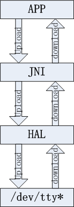
我是直接在HAL层中通过两个线程对串口的设备节点/dev/ttymxc1进行读和写的,相应的代码如下:
1、init代码
/***************************************************************
** fun: init uart(/dev/ttymxc1);
** in:
** out: fd sucess, -1 false;
** init_mcuuart
***************************************************************/
static int init_mcuuart(void)
{
int fd,var;
portinfo pPort_info;
int err;
dbg(DBG_DEBUG,"init_mcuuart in");
//clear message buf memset(&pPort_info,0,sizeof(portinfo));
//alloc sent and receive buf pSentMessagePackage = malloc(sizeof(msgpkg));
pReceiveMessagePackage = malloc(sizeof(msgpkg));
fd=open_mcuport();
pSentMessagePackage->fd= fd;
pReceiveMessagePackage->fd= fd;
if(fd == -1)
{
LOGE("init_mcuuart open port error!");
return -1;
}
pPort_info.baud_rate=COM1MCU_BAUD;
pPort_info.data_bits=COM1MCU_DATABIT;
pPort_info.flow_ctrl=COM1MCU_CTRL;
pPort_info.stop_bit=COM1MCU_STOPBIT;
pPort_info.parity=COM1MCU_PARITY;
pPort_info.port_fd=fd;
//pthread_mutex_lock(&pPort_info.portlock); var = set_portLocked(&pPort_info);
//pthread_mutex_unlock(&pPort_info.portlock);
if(var < 0)
{
LOGE("set_portLocked error!");
return -1;
}
//handshake message//messagePackage(&PowerOnHandShakeCmd,NULL);//messagePackage(&TestCmd,"************com1mcu.c mode for test*********");//uart send message thread sem_init(&pSentMessagePackage->uart_begin, 0, 0);
sem_init(&pSentMessagePackage->uart_end, 0, 0);
pSentMessagePackage->uart_inited = true;
err = pthread_create(&pSentMessagePackage->thread_id, NULL, &uartUploadData, (void *)pSentMessagePackage);
if(err != 0)
LOGE("init_mcuuart pthread_create pSentMessagePackage error %s!",strerror(err));
//uart receive message thread and analyze it//sem_init(&pReceiveMessagePackage->uart_begin, 0, 0); sem_init(&pReceiveMessagePackage->uart_end, 0, 0);
pReceiveMessagePackage->uart_inited = true;
err = pthread_create(&pReceiveMessagePackage->thread_id, NULL, &uartDownloadData, (void *)pReceiveMessagePackage);
if(err != 0)
LOGE("init_mcuuart pthread_create pReceiveMessagePackage error %s!",strerror(err));
return 0;
}
2、发送数据回调函数
/***************************************************************
** fun: uart send handle
** in: arg pSentMessagePackage
**out:
** uartUploadData
****************************************************************/
static void * uartUploadData(void * arg)
{
pMsgPkg upData = (pMsgPkg)arg;
while(1)
{
sem_wait(&upData->uart_begin);
if(!upData->uart_inited)
{
sem_post(&upData->uart_end);
break;
}
//No message to upload if(upData->messageCnt <= 0)
sem_wait(&upData->uart_begin);
upData->SYNCCode = SYNCDATA1;
#if 1
if(!CRCCheck((uuint8*)upData,Send)) //CRC {
LOGE("uartUploadData CRC Error!");
sem_wait(&upData->uart_begin);
}
#endif
//sent message len = SYNCCodeLen(2)+CmdCnt(1)+CmdLen(1)+messageLen(N)+CRCLen(1) send_mcuuart(upData->fd,upData,upData->messageLen+5);
sem_post(&upData->uart_end);
upData->messageCnt = 0;
upData->messageLen = 0;
}
return true;
}
3、接收数据回调函数
/***************************************************************
** fun: uart receive handle
** in: arg pReceiveMessagePackage
** out:
** uartDownloadData
****************************************************************/
static void * uartDownloadData(void * arg)
{
uuint8 buffer[RECMSGONCELEN];
pMsgPkg pmsg = (pMsgPkg)arg;
int len,i;
while(1)
{
if(!pmsg->uart_inited)
{
sem_post(&pmsg->uart_end);
break;
}
recv_mcuuart(pmsg->fd,buffer,&len,RECMSGONCELEN,RECMSGTIMEOUT);
if(len > 0)
{
//copy the receive data to the big buf for(i=0;i
{
if(pmsg->pRecPoint >= RECMSGBUFLEN)
pmsg->pRecPoint = 0;
receiveBuf[pmsg->pRecPoint] = buffer[i];
pmsg->pRecPoint++;
}
memset(buffer,0,RECMSGONCELEN);
}
LOGI("pAnalyzePoint=%d,pRecPoint=%d",pmsg->pAnalyzePoint,pmsg->pRecPoint);
//have new message and prev message have handout to app, analyze from the analyze Point if((pmsg->pAnalyzePoint != pmsg->pRecPoint)&&(!pmsg->handOutFlag))
analyzeMsgPackage(pmsg, &(receiveBuf[pmsg->pAnalyzePoint]));
}
return true;
}
JNI中的代码很简单,通过init、upload、download这三个HAL层中的函数接口对串进行初始化、写数据和读数据。
写数据的时候,直接把java传过来的数据通过upload在HAL中加上数据头及CRC位,然后在写线程中写入串口设备节点……
读数据的时候,在HAL中通过读数据的线程从串口设备节点中将数据读出后进行解析和CRC校验,如果CRC校验正常则把解析之后的数据通过JNI层传给java中进行使用。
值得一提的是接收数据和解析数据的时候相应buffer的控制,我这里在接收数据的时候用的是一个环形buffer,容量为1KByte,这样做的目的的防止接收数据丢失。
JAVA中的代码主要是两部分,一部分是实现写数据的方法,这个比较简单,封闭好JNI中的本地函数uart_upload就行了。别一部分是实现读数据的方法,这个有点麻烦,因为在我的系统里读数据的时候可能有主动上报的数据,也就是ARM这边没有请求,MCU那边如果有数据时会主动上报给ARM,比如MCU那边的按键信息等。我在读的方法里用了一个线程来处理这些,不停的扫描解析数据的buffer,当有正确的数据已经解析并存在于解析buffer中时,就在这个线程里通过广播的方式将消息广播出去,然后在APP中监听这个广播就行了,相应的代码比较多,这里就不发上来了!
最后要强调一点的是,由于操作设备节点的时候,需要有system用户的权限,我是在相应的app的配置文件中增加了android:sharedUserId="android.uid.system"

为开发者提供学习成长、分享交流、生态实践、资源工具等服务,帮助开发者快速成长。
更多推荐


 0
0 0
0- 0


 已为社区贡献2条内容

所有评论(0)